Lighting System Rear Fog Light Circuit
DESCRIPTION
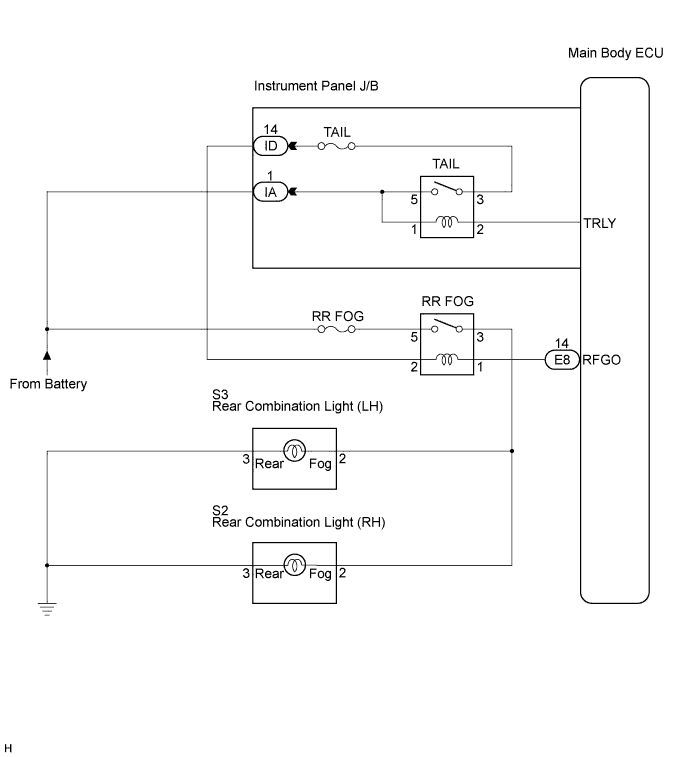
WIRING DIAGRAM
INSPECTION PROCEDURE
PERFORM ACTIVE TEST USING INTELLIGENT TESTER
INSPECT FUSE (RR FOG)
INSPECT REAR FOG LIGHT RELAY
INSPECT INSTRUMENT PANEL JUNCTION BLOCK ASSEMBLY
CHECK HARNESS AND CONNECTOR (INSTRUMENT PANEL J/B ASSEMBLY - REAR FOG LIGHT RELAY)
CHECK HARNESS AND CONNECTOR (REAR FOG LIGHT RELAY - MAIN BODY ECU)
CHECK HARNESS AND CONNECTOR (BATTERY - REAR FOG LIGHT RELAY)
LIGHTING SYSTEM - Rear Fog Light Circuit |
DESCRIPTION
When the taillights are on and the rear fog light switch is turned on, the main body ECU turns the rear fog lights on.
WIRING DIAGRAM
INSPECTION PROCEDURE
| 1.PERFORM ACTIVE TEST USING INTELLIGENT TESTER |
Connect the intelligent tester to the DLC3.
Turn the ignition switch to the ON position and turn the intelligent tester main switch on.
Turn the light control switch to the TAIL position.
Select the item below in the ACTIVE TEST and then check that the relay operates.
Main Body (Main Body ECU):Item
| Test Details
| Diagnostic Note
|
Rear Fog Light Relay
| Rear fog light relay ON/OFF
| -
|
- OK:
- Rear fog light relay operates. (Rear fog lights come on)
| | PROCEED TO NEXT CIRCUIT INSPECTION SHOWN IN PROBLEM SYMPTOMS TABLE |
|
|
Remove the RR FOG fuse from the engine room R/B.
Measure the resistance of the fuse.
- Standard resistance:
- Below 1 Ω
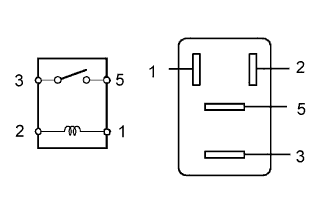
| 3.INSPECT REAR FOG LIGHT RELAY |
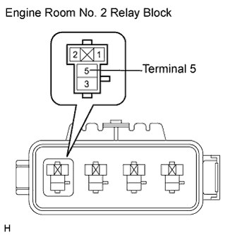
Remove the rear fog light relay from the engine room No. 2 J/B.
Measure the resistance according to the value(s) in the table below.
- Standard resistance:
Tester Connection
| Specified Condition
|
3 - 5
| 10 kΩ or higher
|
Below 1 Ω (When battery voltage is applied to terminals 1 and 2)
|
| | REPLACE REAR FOG LIGHT RELAY |
|
|
| 4.INSPECT INSTRUMENT PANEL JUNCTION BLOCK ASSEMBLY |
Measure the voltage according to the value(s) in the table below.
- Standard voltage:
Tester Connection
| Condition
| Specified Condition
|
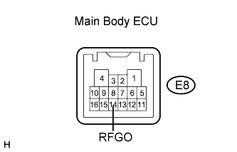
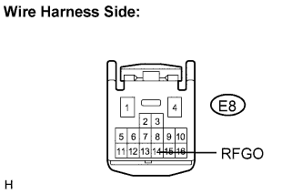
E8-14 - Body ground
| Light control switch in TAIL and rear fog light switch OFF → ON
| 10 to 14 V → Below 1 V
|
| 5.CHECK HARNESS AND CONNECTOR (INSTRUMENT PANEL J/B ASSEMBLY - REAR FOG LIGHT RELAY) |
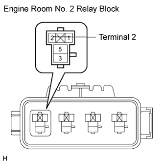
Remove the rear fog light relay from the engine room No. 2 relay block.
Measure the voltage on the relay block side according to the value(s) in the table below.
- Standard voltage:
Tester Connection
| Condition
| Specified Condition
|
Rear fog light relay terminal 2 - Body ground
| Light control switch OFF → TAIL
| 10 to 14 V
|
| | REPAIR OR REPLACE HARNESS OR CONNECTOR |
|
|
| 6.CHECK HARNESS AND CONNECTOR (REAR FOG LIGHT RELAY - MAIN BODY ECU) |
Disconnect the E8 main body ECU connector.
Measure the voltage according to the value(s) in the table below.
- Standard voltage:
Tester Connection
| Condition
| Specified Condition
|
E8-14 - Body ground
| Light control switch OFF → TAIL
| Below 1 V → 10 to 14 V
|
| | REPAIR OR REPLACE HARNESS OR CONNECTOR |
|
|
| OK |
|
|
|
| REPLACE INSTRUMENT PANEL JUNCTION BLOCK ASSEMBLY |
|
| 7.CHECK HARNESS AND CONNECTOR (BATTERY - REAR FOG LIGHT RELAY) |
Remove the rear fog light relay from the engine room No. 2 relay block.
Measure the voltage on the relay block side according to the value(s) in the table below.
- Standard voltage:
Tester Connection
| Condition
| Specified Condition
|
Rear fog light relay terminal 5 - Body ground
| Always
| 10 to 14 V
|
| | REPAIR OR REPLACE HARNESS OR CONNECTOR (BATTERY - REAR FOG LIGHT RELAY) |
|
|
| OK |
|
|
|
| REPAIR OR REPLACE HARNESS OR CONNECTOR (REAR FOG LIGHT RELAY - BODY GROUND) |
|