Forward Clutch Reassembly
INSTALL INPUT SHAFT OIL SEAL RING
INSTALL FORWARD CLUTCH PISTON SUB-ASSEMBLY
INSTALL FORWARD CLUTCH RETURN SPRING SUB-ASSEMBLY
INSTALL FORWARD MULTIPLE DISC CLUTCH DISC
INSPECT PACK CLEARANCE OF FORWARD CLUTCH
INSPECT FORWARD MULTIPLE CLUTCH DISC
Forward Clutch -- Reassembly |
| 1. INSTALL INPUT SHAFT OIL SEAL RING |
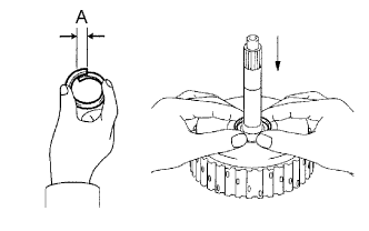
Compress a new input shaft oil seal ring from both sides to adjust dimension A.
- Dimension A:
- 5 mm (0.197 in.)
Coat the oil seal ring with ATF and install it to the input shaft.
- NOTICE:
- Do not expand the gap of the oil seal ring too much. Securely engage the hooks.
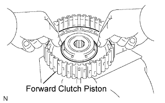
| 2. INSTALL FORWARD CLUTCH PISTON SUB-ASSEMBLY |
Coat the forward clutch piston with ATF, and install it to the input shaft.
- NOTICE:
- Be careful not to damage the lip seal of the forward clutch piston.
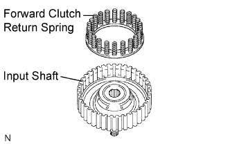
| 3. INSTALL FORWARD CLUTCH RETURN SPRING SUB-ASSEMBLY |
Install the return spring to the input shaft.
- NOTICE:
- After installing the spring sub-assembly, check all of the springs are fitted in the piston correctly.
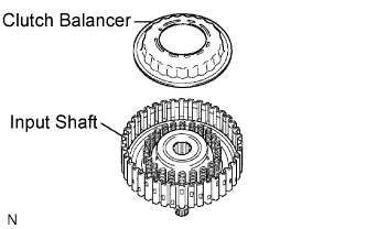
Coat the clutch balancer with ATF.
Install the clutch balancer to the input shaft.
- NOTICE:
- Be careful not to damage the lip seal of the forward clutch balancer.
- Install the clutch balancer carefully not to have a pinching or any other defects at the sealing lip.
- Apply enough ATF to the sealing lip prior to installation.
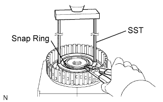
Place SST on the clutch balancer, and compress the clutch balancer with a press.
- SST
- 09387-00020
Install the snap ring with a snap ring expander.
- NOTICE:
- Stop the press when the spring seat is lowered to the place 1 to 2 mm (0.039 to 0.078 in.) from the snap ring groove. This prevents the spring seat from being deformed.
- Do not expand the snap ring excessively.
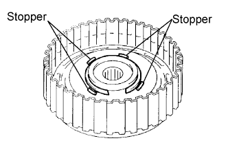
Position the end gap of the snap ring in the piston as shown in the illustration.
- NOTICE:
- The end gap of the snap ring should not be aligned with any of the stoppers.
| 4. INSTALL FORWARD MULTIPLE DISC CLUTCH DISC |
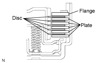
Coat the 5 discs with ATF.
Install the 5 plates, 5 discs, and flange to the input shaft.
- NOTICE:
- Be careful about the order of discs, plates, and flange.
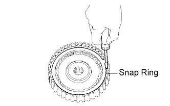
Using a screwdriver, install the snap ring.
Check that the end gap of the snap ring is not aligned with one of the cutouts.
- NOTICE:
- The snap ring should be securely engaged in the groove of the drum.
| 5. INSPECT PACK CLEARANCE OF FORWARD CLUTCH |
Install the forward clutch on the oil pump.
- NOTICE:
- Be careful not to damage the oil seal ring of the oil pump.
Using a dial indicator, measure the forward clutch pack clearance while applying and releasing compressed air (392 kPa, 4.0 kgf/cm2, 57 psi).
- Pack clearance:
- 1.00 to 1.25 mm (0.0394 to 0.04921 in.)
If the clearance is not within the standard, inspect the discs, plates and flange.
If the piston stroke is less than the minimum, parts may have been assembled incorrectly. Check and reassemble again.
- HINT:
- As the opening is large, cover it with a piece of cloth or shop rag to prevent the compressed air from being released.
- There are 5 different thicknesses of flanges available.
Flange thickness: mm (in.)No.
| Thickness
| No.
| Thickness
|
1
| 3.00 (0.1181)
| 4
| 3.45 (0.1358)
|
2
| 3.15 (0.1240)
| 5
| 3.60 (0.1417)
|
3
| 3.30 (0.1299)
| -
| -
|
| 6. INSPECT FORWARD MULTIPLE CLUTCH DISC |
Check if the disc lightly rotates when rotating the forward clutch assembly after inserting the multiple disc clutch into it.
- NOTICE:
- Do not place the forward clutch assembly in a vise.