Rear View Monitor System -- Terminals Of Ecu |
| REAR TELEVISION CAMERA ASSEMBLY (w/o Entry and Start System) |
Disconnect the S19 connector from the rear television camera assembly.

Measure the voltage of each terminal of the wire harness side connector.
If the result is not as specified, there may be a malfunction on the wire harness side.Terminal No. (Symbol) Wiring Color Terminal Description Condition Specified Condition S19-1 (CGND) - Body ground Shield - Body ground Ground Always Below 1 V S19-5 (CB+) - S19-1 (CGND) B - Shielded Power source Ignition switch ON
Shift lever in R5.5 to 7 V Reconnect the S19 connector to the rear television camera assembly.
Check for pulses between each terminal of the connector.
If the result is not as specified, the camera may have a malfunction.Terminal No. (Symbol) Wiring Color Terminal Description Condition Specified Condition S19-6 (CV+) - S19-2 (CV-) R - W Display signal Ignition switch ON
Shift lever in R
Under normal conditionsPulse generation
(See waveform 1)Ignition switch ON
Shift lever in R
Camera lens covered, blacking out screenPulse generation
(See waveform 2)Reference (Oscilloscope waveform):
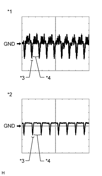
Waveform 1 (under normal conditions)
Item Content Terminal No. (Symbol) S19-6 (CV+) - S19-2 (CV-) Tool Setting 200 mV/DIV., 50 μsec./DIV. Condition Ignition switch ON, shift lever in R - HINT:
- The video waveform changes according to the image sent by the rear television camera assembly.
Waveform 2 (camera lens is covered, blacking out the screen)
Item Content Terminal No. (Symbol) S19-6 (CV+) - S19-2 (CV-) Tool Setting 200 mV/DIV., 50 μsec./DIV. Condition Ignition switch ON, shift lever in R - HINT:
- The video waveform changes according to the image sent by the rear television camera assembly.
Text in Illustration *1 Waveform 1 (under normal conditions) *2 Waveform 2 (camera lens is covered, blacking out the screen) *3 Synchronized Signal *4 Video Waveform
 |
| REAR TELEVISION CAMERA ASSEMBLY (w/ Entry and Start System) |
Disconnect the connector from the rear television camera assembly.

Measure the voltage of each terminal of the wire harness side connector.
If the result is not as specified, there may be a malfunction on the wire harness side.Terminal No. (Symbol) Terminal Description Condition Specified Condition 6 (CGND) - Body ground Ground Always Below 1 V 3 (CB+) - 6 (CGND) Power source Ignition switch ON
Shift lever in R5.5 to 7 V Reconnect the connector to the rear television camera assembly.
Check for pulses between each terminal of the connector.
Terminal No. (Symbol) Terminal Description Condition Specified Condition 1 (CV+) - 4 (CV-) Display signal Ignition switch ON
Shift lever in R
Under normal conditionsPulse generation
(See waveform 1)Ignition switch ON
Shift lever in R
Camera lens covered, blacking out screenPulse generation
(See waveform 2)- HINT:
- A waterproof connector is used for the rear television camera assembly. Therefore, inspect the waveform at the navigation receiver assembly with the connector connected.
Reference (Oscilloscope waveform):
- HINT:
- A waterproof connector is used for the rear television camera assembly. Therefore, inspect the waveform at the navigation receiver assembly with the connector connected.
Waveform 1 (under normal conditions)
Item Content Terminal No. (Symbol) 1 (CV+) - 4 (CV-) Tool Setting 200 mV/DIV., 50 μsec./DIV. Condition Ignition switch ON, shift lever in R - HINT:
- The video waveform changes according to the image sent by the rear television camera assembly.
Waveform 2 (camera lens is covered, blacking out the screen)
Item Content Terminal No. (Symbol) 1 (CV+) - 4 (CV-) Tool Setting 200 mV/DIV., 50 μsec./DIV. Condition Ignition switch ON, shift lever in R - HINT:
- The video waveform changes according to the image sent by the rear television camera assembly.
Text in Illustration *1 Waveform 1 (under normal conditions) *2 Waveform 2 (camera lens is covered, blacking out the screen) *3 Synchronized Signal *4 Video Waveform
|
| NAVIGATION RECEIVER ASSEMBLY (CAMRY_ACV40 RM0000011BQ05AX.html) |