Automatic Transaxle System Terminals Of Ecu
TCM
ECM
Automatic Transaxle System -- Terminals Of Ecu |
- HINT:
- Each TCM terminal's standard voltage is shown in the table below.
- In the table, first follow the information under "Condition". Look under "Symbols (Terminal No.)" for the terminals to be inspected. The standard voltage between the terminals is shown under "Specific Condition".
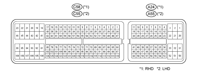
- Use the illustration above as a reference for the TCM terminals.
Symbols (Terminals No.)
| Wiring Color
| Terminal Description
| Condition
| Specified Condition
|
R (C56-15) - E1 (C56-8)
| W - B-W
| R shift position switch signal
| Ignition switch ON and shift lever in R position
| 10 to 14 V
|
Ignition switch ON and shift lever in any position except R position
| Below 1 V
|
D (C56-16) - E1 (C56-8)
| R - B-W
| D shift position switch signal
| Ignition switch ON and shift lever in D or 3 position
| 10 to 14 V
|
Ignition switch ON and shift lever in any position except D and 3 position
| Below 1 V
|
STP (C56-12) - E1 (C56-8)
| B - B-W
| Stop light switch signal
| Brake pedal is depressed
| 7.5 to 14 V
|
Brake pedal is released
| Below 1.5 V
|
NSW (C56-11) - E1 (C56-8)
| L - B-W
| Park / neutral switch signal
| Ignition switch ON and shift lever in P or N position
| Below 2 V
|
Ignition switch ON and shift lever in any position except P or N position
| 10 to 14 V
|
STA (C56-10) - E1 (C56-8)
| Y - B-W
| Starter signal
| Cranking (shift lever position in P or N position, ignition switch START)
| 10 to 14 V
|
Ignition switch ON and shift lever in any position except P or N position
| Below 2 V
|
SPD1 (C56-3) - E1 (C56-8)
| BR - B-W
| Speed signal from combination meter
| Vehicle speed 12 mph (20 km/h)
| Pulse generation
(See waveform 1)
|
BATT (C56-1) - E1 (C56-8)
| W-L - B-W
| Battery (for measuring battery voltage and for TCM memory)
| Always
| 9 to 14 V
|
IG2 (C56-13) - E1 (C56-8)
| L-B - B-W
| Ignition switch
| Ignition switch ON
| 9 to 14 V
|
+B (C56-18) - E1 (C56-8)
| W-L - B-W
| Power source of TCM
| Ignition switch ON
| 9 to 14 V
|
CAN+ (C56-6) - E1 (C56-8)
| B - B-W
| CAN communication line
| Ignition switch ON
| Pulse generation
(See waveform 2)
|
CAN- (C56-7) - E1 (C56-8)
| Y - B-W
| CAN communication line
| Ignition switch ON
| Pulse generation
(See waveform 3)
|
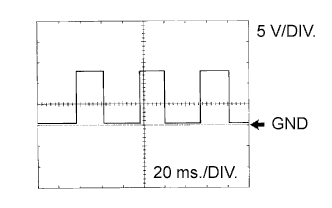
Waveform 1
Reference:Terminal
| SPD1 - E1
|
Tool setting
| 2 V/DIV, 20 ms./DIV
|
Vehicle condition
| Vehicle speed 12 mph (20 km/h)
|
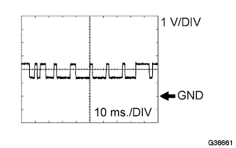
Waveform 2
Reference:Terminal
| CAN+ - E1
|
Tool setting
| 1 V/DIV, 10 ms./DIV
|
Vehicle condition
| Engine is stopped, ignition ON
|
Waveform 3
Reference:Terminal
| CAN- - E1
|
Tool setting
| 1 V/DIV, 10 ms./DIV
|
Vehicle condition
| Engine is stopped, ignition ON
|
- HINT:
- Each ECM terminal's standard voltage is shown in the table below.
- In the table, first follow the information under "Condition". Look under "Symbols (Terminal No.)" for the terminals to be inspected. The standard voltage between the terminals is shown under "Specific Condition".
- Use the illustration above as a reference for the ECM terminals.
RHD:Symbols (Terminals No.)
| Wiring Color
| Terminal Description
| Condition
| Specified Condition
|
S (A24-25) - E1 (C58-81)
| Y - W-B
| S shift position switch signal
| IG switch ON and shift lever in S position
| 10 to 14 V
|
IG switch ON and shift lever in any position except S position
| Below 1 V
|
SFTU (A24-16) - E1 (C58-81)
| R - W-B
| Up shift switch signal
| IG switch ON and shift lever in S position
| 10 to 14 V
|
IG switch ON and shift lever in "+" position (Up shift)
| Below 1 V
|
SFTD (A24-51) - E1 (C58-81)
| L - W-B
| Down shift switch signal
| IG switch ON and shift lever in S position
| 10 to 14 V
|
IG switch ON and shift lever in "-" position (Down shift)
| Below 1 V
|
LHD:Symbols (Terminals No.)
| Wiring Color
| Terminal Description
| Condition
| Specified Condition
|
S (A55-25) - E1 (C55-81)
| Y - W-B
| S shift position switch signal
| IG switch ON and shift lever in S position
| 10 to 14 V
|
IG switch ON and shift lever in any position except S position
| Below 1 V
|
SFTU (A55-16) - E1 (C55-81)
| R - W-B
| Up shift switch signal
| IG switch ON and shift lever in S position
| 10 to 14 V
|
IG switch ON and shift lever in "+" position (Up shift)
| Below 1 V
|
SFTD (A55-51) - E1 (C55-81)
| L - W-B
| Down shift switch signal
| IG switch ON and shift lever in S position
| 10 to 14 V
|
IG switch ON and shift lever in "-" position (Down shift)
| Below 1 V
|