Meter / Gauge System Fuel Receiver Gauge Malfunction
Meter. Camry. Acv40 Gsv40
DESCRIPTION
WIRING DIAGRAM
INSPECTION PROCEDURE
CHECK CAN COMMUNICATION SYSTEM
PERFORM ACTIVE TEST USING INTELLIGENT TESTER
READ VALUE USING INTELLIGENT TESTER
CHECK HARNESS AND CONNECTOR (COMBINATION METER - FUEL SENDER GAUGE ASSEMBLY)
INSPECT FUEL SENDER GAUGE ASSEMBLY
REPLACE COMBINATION METER ASSEMBLY
METER / GAUGE SYSTEM - Fuel Receiver Gauge Malfunction |
DESCRIPTION
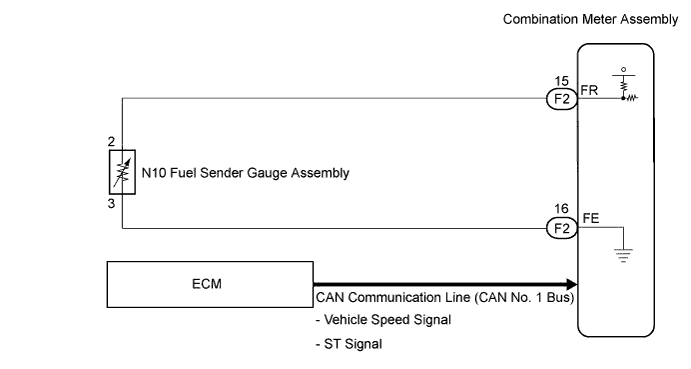
- The meter CPU uses the fuel sender gauge assembly to determine the level of the fuel in the fuel tank. The resistance of the fuel sender gauge will vary between approximately 15 Ω with the float at the full position, and 410 Ω with the float at the empty position. The meter outputs battery voltage through two 820 Ω resistors that are mounted in parallel inside the meter ECU. The meter CPU measures the voltage between the variable resistor in the fuel sender gauge and the two resistors mounted in parallel in the meter. Voltage measured at this point will vary as the float of the fuel sender gauge is moved. The highest voltage observed should be approximately half of battery voltage.
- HINT:
- The fuel level warning light will come on when the fuel level is below 10.5 liters.
WIRING DIAGRAM
INSPECTION PROCEDURE
| 1.CHECK CAN COMMUNICATION SYSTEM |
Check if CAN communication DTC is output (CAMRY_ACV40 RM000000WIB09JX.htmlfor LHD, CAMRY_ACV40 RM000000WIB09KX.html for RHD).
- Result:
| | GO TO CAN COMMUNICATION SYSTEM |
|
|
| 2.PERFORM ACTIVE TEST USING INTELLIGENT TESTER |
Connect the intelligent tester to the DLC3.
Turn the ignition switch to the ON position.
Turn the tester ON.
Enter following menus: Diagnosis / OBD/MOBD / Combination Meter / Active Test.
Check the operation by referring to the table below.
Combination Meter:Tester Display
| Test Part
| Control Range
| Normal Condition
|
Fuel Meter Operation
| Fuel receiver gauge
| EMPTY, 1/2, FULL
| -
|
- OK:
- Needle indication is normal.
| | REPLACE COMBINATION METER ASSEMBLY |
|
|
| 3.READ VALUE USING INTELLIGENT TESTER |
Connect the intelligent tester to the DLC3.
Turn the ignition switch to the ON position.
Turn the tester ON.
Enter following menus: Diagnosis / OBD/MOBD / Combination Meter / Data List.
Check the values by referring to the table below.
Combination Meter:Tester Display
| Measurement Item/Range
| Normal Condition
| Diagnostic Note
|
Fuel Input
| Fuel input signal Min.: 0, Max.: 255
| Fuel gauge indicates (F): 35
Fuel gauge indicates (3/4): 85
Fuel gauge indicates (1/2): 145
Fuel gauge indicates (3/4): 186
Fuel gauge indicates (E): 205
| -
|
- OK:
- Fuel value signal displayed on the tester is almost the same as needle indication.
| | REPLACE COMBINATION METER ASSEMBLY |
|
|
| 4.CHECK HARNESS AND CONNECTOR (COMBINATION METER - FUEL SENDER GAUGE ASSEMBLY) |
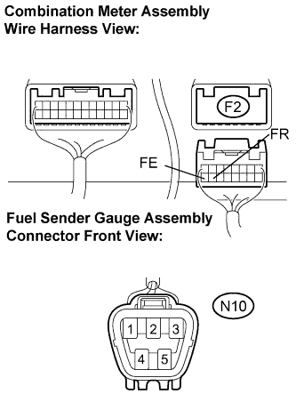
Disconnect the F2 and N10 connectors.
Measure the resistance according to the value(s) in the table below.
- Standard resistance:
Tester Connection
| Condition
| Specified Condition
|
F2-15 (FR) - N10-2
| Always
| Below 1 Ω
|
F2-16 (FE) - N10-3
| Always
| Below 1 Ω
|
N10-2 - Body ground
| Always
| 10 kΩ or higher
|
F2-16 - Body ground
| Always
| 10 kΩ or higher
|
| | REPAIR OR REPLACE HARNESS OR CONNECTOR |
|
|
| 5.INSPECT FUEL SENDER GAUGE ASSEMBLY |
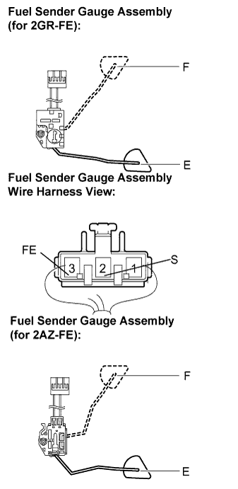
Disconnect the fuel sender gauge connector.
Remove the fuel sender gauge assembly.
Check that the float moves smoothly between F and E.
Measure the resistance between the terminals 2 (S) and 3 (FE) of connector according to the value(s) in the table below.
- Standard resistance:
Float Level
| Resistance (Ω)
|
F
| 13.5 to 16.5
|
Between E and F
| 13.5 to 414.5 (Gradually changes)
|
E
| 405.5 to 414.5
|
| | REPLACE FUEL SENDER GAUGE ASSEMBLY |
|
|
| 6.REPLACE COMBINATION METER ASSEMBLY |
Replace the combination meter assembly with a new one or a normal one.
- OK:
- The operation of the combination meter assembly returns to normal.