Meter / Gauge System Speedometer Malfunction
Meter. Camry. Acv40 Gsv40
DESCRIPTION
WIRING DIAGRAM
INSPECTION PROCEDURE
CHECK CAN COMMUNICATION SYSTEM
PERFORM ACTIVE TEST USING INTELLIGENT TESTER
READ VALUE USING INTELLIGENT TESTER
READ VALUE USING INTELLIGENT TESTER
REPLACE SKID CONTROL ECU
METER / GAUGE SYSTEM - Speedometer Malfunction |
DESCRIPTION
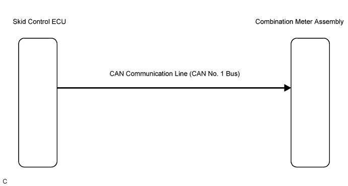
The meter CPU receives vehicle speed signals from the skid control ECU via the CAN communication lines (CAN No. 1 Bus). The vehicle speed sensor detects the voltage that varies according to the vehicle speed. The skid control ECU supplies power to the vehicle speed sensor. The skid control ECU detects vehicle speed signals based on the pulses of the voltage.
WIRING DIAGRAM
INSPECTION PROCEDURE
| 1.CHECK CAN COMMUNICATION SYSTEM |
Check if CAN communication DTC is output (CAMRY_ACV40 RM000000WIB05NX.htmlfor LHD, CAMRY_ACV40 RM000000WIB05SX.html for RHD).
- Result:
| | GO TO CAN COMMUNICATION SYSTEM |
|
|
| 2.PERFORM ACTIVE TEST USING INTELLIGENT TESTER |
Connect the intelligent tester to the DLC3.
Turn the ignition switch to the ON position.
Turn the tester ON.
Enter the following menus: Diagnosis / OBD/MOBD / Combination Meter / Active Test.
Check the operation by referring to the values in the table below.
Combination Meter:Tester Display
| Test Part
| Control Range
| Normal Condition
|
Speed Meter Operation
| Speedometer
| 0, 40, (24), 80 (48), 120 (72), 160 (96), 200 (120) km/h (mph)
| -
|
- OK:
- Needle indication is normal.
| | REPLACE COMBINATION METER ASSEMBLY |
|
|
| 3.READ VALUE USING INTELLIGENT TESTER |
Connect the intelligent tester to the DLC3.
Turn the ignition switch to the ON position.
Turn the tester ON.
Enter the following menus: Diagnosis / OBD/MOBD / Combination Meter / Data List.
Check the values by referring to the values in the table below.
Combination Meter:Tester Display
| Measurement Item/Range
| Normal Condition
| Diagnostic Note
|
Vehicle Speed Meter
| Vehicle speed/Min.: 0 km/h (0 mph), Max.: 255 km/h (158 mph)
| Almost same as actual speed (When driving)
| If data received from the skid control ECU exceeds the range that can be displayed on the meter, the meter continues to display the maximum value of the range.
|
- OK:
- Vehicle speed displayed on the tester is almost the same as the actual vehicle speed measured using a speedometer tester (calibrated chassis dynamometer).
| OK |
|
|
|
| REPLACE COMBINATION METER ASSEMBLY |
|
| 4.READ VALUE USING INTELLIGENT TESTER |
Connect the intelligent tester to the DLC3.
Turn the ignition switch to the ON position.
Turn the tester ON.
Enter the following menus: Diagnosis / OBD/MOBD / ABS/TRAC/VSC / Data List.
Check the values by referring to the table below.
ABS/TRAC/VSC:Tester Display
| Measurement Item/Range
| Normal Condition
| Diagnostic Note
|
FR/FL/RR/RL Wheel Speed
| Vehicle speed/Min.: 0 km/h (0 mph), Max.: 326 km/h (202 mph)
| Almost same as actual speed (When driving)
| -
|
- OK:
- Vehicle speed displayed on the tester is almost the same as the actual vehicle speed.
| | GO TO BRAKE CONTROL SYSTEM |
|
|
| 5.REPLACE SKID CONTROL ECU |
Replace the skid control ECU with a new or a normal one.
- OK:
- The operation of the speedometer returns to normal.
| | REPLACE COMBINATION METER ASSEMBLY |
|
|