Toyota Parking Assist-Sensor System -- Operation Check |
| SELF-CHECK FUNCTION INSPECTION |
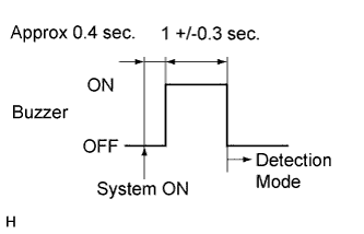
Initial check
Turn the ignition switch to ON.
Turn the clearance sonar main switch on.
- Standard:
- Approximately 0.4 seconds after the main switch is turned on, the buzzers sound for 1 +/- 0.3 seconds, and then the back sonar sensors and clearance sonar sensors change to detection mode.
- HINT:
- If the system detects an open circuit in a sensor circuit, or a sensor does not work, the buzzer will sound to warn of a sensor malfunction after the initial check.
- If a buzzer does not sound, inspect the clearance warning buzzer circuit (CAMRY_ACV40 RM000002KWU00UX.html).
Buzzer operation for sensor malfunction warning
If the system detects an open circuit in a sensor circuit, or a sensor does not work, the buzzer will sound using an intermittent pattern that indicates the position of the malfunction.
Either a sensor circuit with an open circuit or a sensor that does not work can be determined easily by listening to the sound and pattern of the buzzer. When the buzzer sounds, inspect the relevant position according to the following tables.
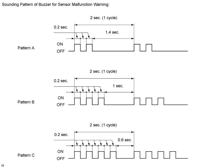
- Pattern A:
Sounding Buzzer Suspected Area Clearance Warning Buzzer
(for Corner Sensors)- Front right sensor or circuit
- Rear right sensor or circuit
Clearance Warning Buzzer
(for Back Sensors)Rear right center sensor or circuit - Front right sensor or circuit
- Pattern B:
Sounding Buzzer Suspected Area Clearance Warning Buzzer
(for Corner Sensors)- Front left sensor or circuit
- Rear left sensor or circuit
Clearance Warning Buzzer
(for Back Sensors)Rear left center sensor or circuit - Front left sensor or circuit
- Pattern C:
Sounding Buzzer Suspected Area Clearance Warning Buzzer
(for Corner Sensors)- Front right sensor or circuit
- Front left sensor or circuit
- Rear right sensor or circuit
- Rear left sensor or circuit
Clearance Warning Buzzer
(for Back Sensors)- Rear right center sensor or circuit
- Rear left center sensor or circuit
- Front right sensor or circuit
- HINT:
- If sensors from the Suspected Areas of both pattern A and pattern B (for corner sensors) are malfunctioning, the corner sensor buzzer will sound pattern C. If sensors from the Suspected Areas of both pattern A and pattern B (for back sensors) are malfunctioning, the back sensor buzzer will sound pattern C.
- The buzzer(s) will stop when the malfunctioning sensor returns to normal.
| DETECTION RANGE MEASUREMENT CHECK |
Turn the ignition switch to ON do not start the engine.
Move the shift lever to R.
- NOTICE:
- The corner sensors do not work with the parking brake on. Use wheel chocks or equivalent to secure the vehicle.
Turn the clearance sonar main switch on.
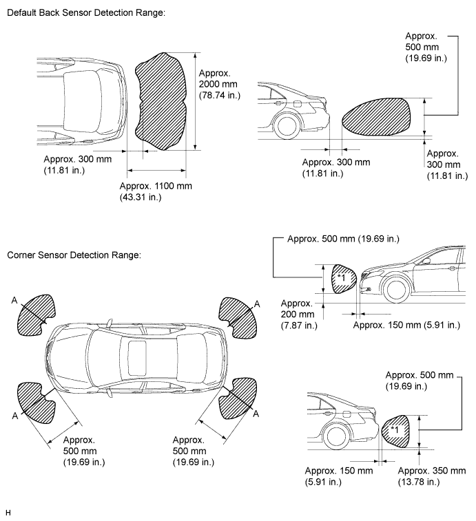
Move a 60 mm (2.36 in.) diameter pole around the sensors to measure the detection range of the sensors.
- NOTICE:
- The measured detection ranges are for a 60 mm (2.36 in.) diameter pole. The detection ranges for walls and other obstacles are different.
- The No. 1 ultrasonic sensor side view detection range hatched area (labeled*1) represents the cross section of the top view detection range A lines. The hatched area*1 does not represent the entire side view detection range.
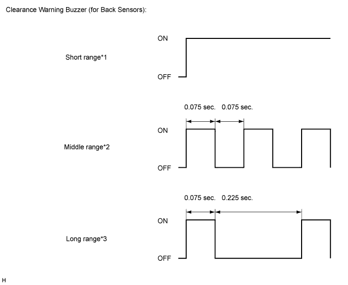
Check the sound of the buzzer when the back sonar sensors detect an obstacle.
- Operation Condition:
Ignition Switch Clearance Sonar Main Switch Shift Position ON ON R
- HINT:
- Since sound waves are used for detection range measurement, the detection ranges may vary slightly due to the outside air temperature.
- *1: Short Range
Detection Range Connector Condition Obstacle Within 500 +/- 50 mm
(19.69 +/- 1.97 in.)Connected Pole Within 700 +/- 70 mm
(27.56 +/- 2.76 in.)Disconnected Pole - *2: Middle Range
Detection Range Connector Condition Obstacle From 500 +/- 50 mm (19.69 +/- 1.97 in.) to 1000 +/- 100 mm (39.37 +/- 3.94 in.) Connected Pole From 700 +/- 70 mm(27.56 +/- 2.76 in.) to 1000 +/- 100 mm (39.37 +/- 3.94 in.) Disconnected Pole - *3: Long Range
Detection Range Connector Condition Obstacle From 1000 +/- 100 mm (39.37 +/- 3.94 in.) to 1500 +/- 150 (59.06 +/- 5.91 in.) Connected or disconnected Wall
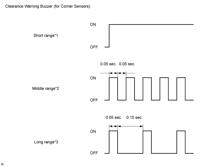
Check the sound of the buzzer when the corner sensors detect an obstacle.
- Operation Condition:
Ignition Switch Clearance Sonar Main Switch Parking Brake Vehicle Speed ON ON OFF 10 km/h (6.2 mph) or less
- HINT:
- Since sound waves are used for detection range measurement, the detection ranges may vary slightly due to the outside air temperature.
- *1: Short Range
Detection Range Connector Condition Obstacle Within 250 +/- 30 mm
(9.84 +/- 1.18 in.)Connected or disconnected Pole - *2: Middle Range
Detection Range Connector Condition Obstacle From 250 +/- 30 mm (9.84 +/- 1.18 in.) to 375 +/- 40 (14.76 +/- 1.57 in.) Connected or disconnected Pole - *3: Long Range
Detection Range Connector Condition Obstacle From 375 +/- 40 mm (14.76 +/- 1.57 in.) to 500 +/- 50 (19.69 +/- 1.97 in.) Connected or disconnected Pole