Audio And Visual System Speaker Circuit
DESCRIPTION
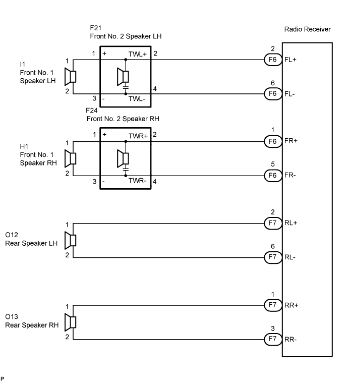
WIRING DIAGRAM
INSPECTION PROCEDURE
CHECK HARNESS AND CONNECTOR
INSPECT FRONT NO. 1 SPEAKER
INSPECT FRONT NO. 2 SPEAKER
INSPECT REAR SPEAKER
AUDIO AND VISUAL SYSTEM - Speaker Circuit |
DESCRIPTION
When the vehicle has a built-in type amplifier, a sound signal is sent from the radio receiver to the speakers via this circuit.
WIRING DIAGRAM
INSPECTION PROCEDURE
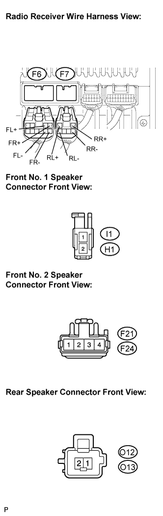
| 1.CHECK HARNESS AND CONNECTOR |
Disconnect the connectors shown in the illustration from the radio receiver and speakers.
Measure the resistance between each of the front No. 2 speakers and the radio receiver to check for an open circuit in the wire harness.
- Standard resistance:
- Below 1 Ω
Measure the resistance between each of the front No. 2 speakers and each of the front No. 1 speakers to check for an open circuit in the wire harness.
- Standard resistance:
- Below 1 Ω
Measure the resistance between each of the rear speakers and the radio receiver to check for an open circuit in the wire harness.
- Standard resistance:
- Below 1 Ω
Measure the resistance between each speaker and body ground to check for a short circuit in the wire harness.
- Standard resistance:
- 10 kΩ or higher
| | REPAIR OR REPLACE HARNESS OR CONNECTOR |
|
|
| 2.INSPECT FRONT NO. 1 SPEAKER |
Resistance check.
Measure the resistance between the terminals of the speaker.
- Standard resistance:
- Approximately 4 Ω
| | REPLACE FRONT NO. 1 SPEAKER |
|
|
| 3.INSPECT FRONT NO. 2 SPEAKER |
Check that the malfunction disappears when another speaker in good condition is installed.
- Standard:
- Malfunction disappears.
- HINT:
- Connect all the connectors to the front No. 2 speaker.
- When there is a possibility that either the right or left front speaker is defective, inspect by interchanging the right one with the left one.
- Perform the above inspection on both LH and RH sides.
| | REPLACE FRONT NO. 2 SPEAKER |
|
|
Resistance check.
Measure the resistance between the terminals of the speaker.
- Standard resistance:
- Approximately 4 Ω
| OK |
|
|
|
| PROCEED TO NEXT CIRCUIT INSPECTION SHOWN IN PROBLEM SYMPTOMS TABLE |
|