Lighting System Door Lock Position Circuit
DESCRIPTION
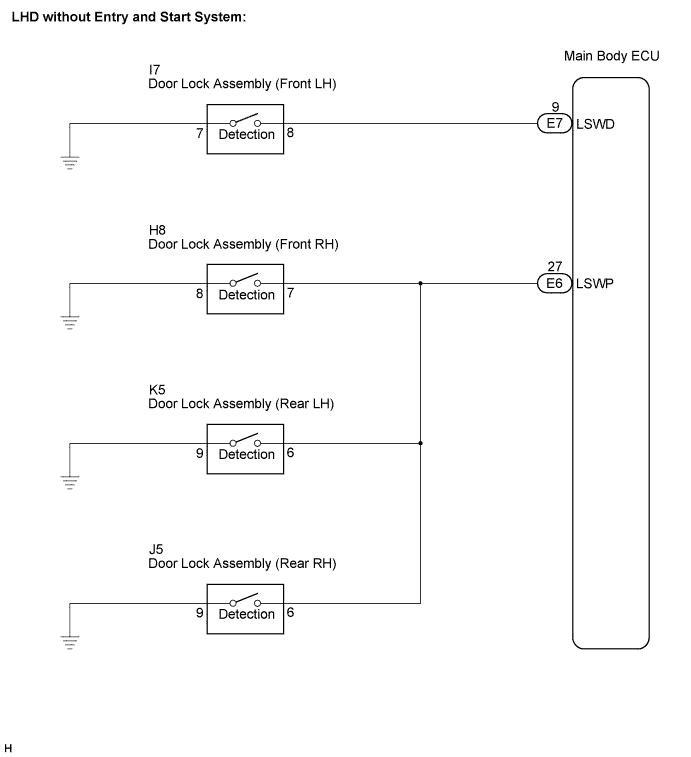
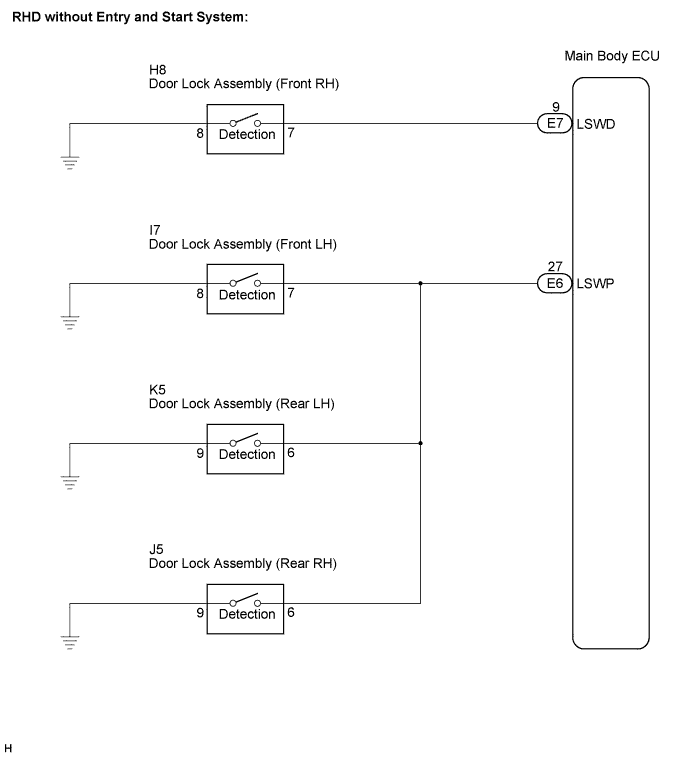
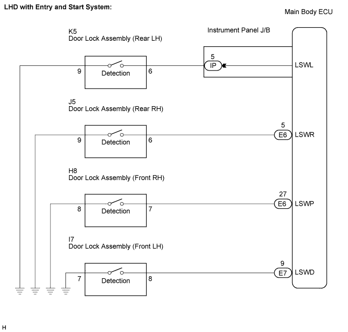
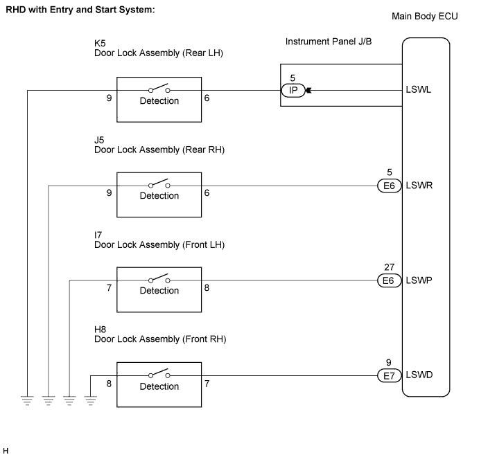
WIRING DIAGRAM
INSPECTION PROCEDURE
READ VALUE USING INTELLIGENT TESTER
LIGHTING SYSTEM - Door LOCK Position Circuit |
DESCRIPTION
The main body ECU receives each door lock position switch signal to control the illuminated entry system.
WIRING DIAGRAM
INSPECTION PROCEDURE
| 1.READ VALUE USING INTELLIGENT TESTER |
Connect the intelligent tester to the DLC3.
Turn the ignition switch to the ON position and turn the intelligent tester main switch on.
Select the items below in the DATA LIST, and read the display on the intelligent tester.
Main Body (Main Body ECU): without Entry and Start SystemItem
| Measurement Item / Display (Range)
| Normal Condition
| Diagnostic Note
|
D-Door Lock Pos SW
| Driver side door lock position switch signal / ON or OFF
| ON: Driver side door is unlocked
OFF: Driver side door is locked
| -
|
P-Door Lock Pos SW
| Passenger side door lock position switch signal / ON or OFF
| ON: Passenger side door or rear LH door or rear RH door is unlocked
OFF: Passenger side door and rear LH door and rear RH door doors are locked
| -
|
Main Body (Main Body ECU): (with Entry and Start System)Tester Display
| Measurement Item / Display (Range)
| Normal Condition
| Diagnostic Note
|
D-Door Lock Pos SW
| Driver side door lock position switch signal / ON or OFF
| ON: Driver side door is unlocked
OFF: Driver side door is locked
| -
|
P-Door Lock Pos SW
| Passenger side door lock position switch signal / ON or OFF
| ON: Passenger side door is unlocked
OFF: Passenger side door is locked
| -
|
RR-Door Lock Pos SW
| Rear right door lock position switch signal / ON or OFF
| ON: Rear right door is unlocked
OFF: Rear right door is locked
| -
|
RL-Door Lock Pos SW
| Rear left door lock position switch signal / ON or OFF
| ON: Rear left door is unlocked
OFF: Rear left door is locked
| -
|
- OK:
- Normal conditions listed above are displayed.
| | GO TO POWER DOOR LOCK CONTROL SYSTEM |
|
|
| OK |
|
|
|
| PROCEED TO NEXT CIRCUIT INSPECTION SHOWN IN PROBLEM SYMPTOMS TABLE |
|