Rear No. 1 Suspension Arm Installation
INSTALL REAR NO. 1 SUSPENSION ARM LH
INSTALL REAR SUSPENSION MEMBER SUB-ASSEMBLY
INSTALL REAR SUSPENSION MEMBER LOWER STOPPER LH
INSTALL REAR SUSPENSION MEMBER LOWER STOPPER RH
TEMPORARILY TIGHTEN REAR NO. 1 SUSPENSION ARM LH
TEMPORARILY TIGHTEN REAR NO. 1 SUSPENSION ARM RH
TEMPORARILY TIGHTEN REAR NO. 2 SUSPENSION ARM LH
TEMPORARILY TIGHTEN REAR NO. 2 SUSPENSION ARM RH
TEMPORARILY TIGHTEN REAR STRUT ROD
STABILIZE SUSPENSION
FULLY TIGHTEN REAR NO. 1 SUSPENSION ARM LH
FULLY TIGHTEN REAR NO. 1 SUSPENSION ARM RH
FULLY TIGHTEN REAR NO. 2 SUSPENSION ARM LH
FULLY TIGHTEN REAR NO. 2 SUSPENSION ARM RH
FULLY TIGHTEN REAR STRUT ROD
INSTALL REAR STABILIZER BUSHING
INSTALL REAR STABILIZER BAR NO. 2 BRACKET
INSTALL REAR STABILIZER BAR NO. 1 BRACKET
INSTALL REAR STABILIZER BAR
INSTALL REAR STABILIZER LINK ASSEMBLY LH
INSTALL REAR STABILIZER LINK ASSEMBLY RH
INSTALL CENTER EXHAUST PIPE ASSEMBLY (for 2AZ-FE)
INSTALL CENTER EXHAUST PIPE ASSEMBLY (for 2GR-FE)
INSTALL TAIL EXHAUST PIPE ASSEMBLY (for 2GR-FE)
INSTALL REAR WHEEL
CHECK FOR EXHAUST GAS LEAKAGE
INSPECT AND ADJUST REAR WHEEL ALIGNMENT
Rear No. 1 Suspension Arm -- Installation |
| 1. INSTALL REAR NO. 1 SUSPENSION ARM LH |
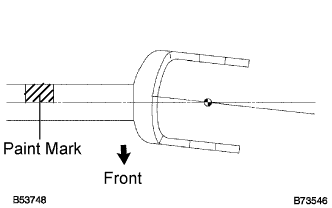
Install the rear No. 1 suspension arm (inner side) with the bolt, and temporarily tighten the bolt.
Install the rear No. 1 suspension arm so that the bracket leans toward the front side of the vehicle as shown in the illustration.
Ensure that the paint mark faces the rear side of the vehicle.
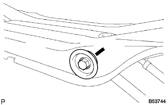
Set the rear No.1 suspension arm in the position shown in the illustration, and fully tighten the bolt.
- Torque:
- 100 N*m{1,020 kgf*cm, 74 ft.*lbf}
| 2. INSTALL REAR SUSPENSION MEMBER SUB-ASSEMBLY |
Raise the rear suspension member with a jack.
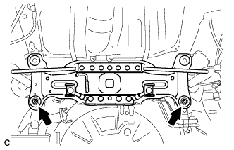
Install the rear suspension member with the 2 bolts.
- Torque:
- 56 N*m{571 kgf*cm, 41 ft.*lbf}
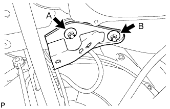
| 3. INSTALL REAR SUSPENSION MEMBER LOWER STOPPER LH |
Install the rear suspension member lower stopper LH with the 2 nuts.
- Torque:
- Nut A:
- 55 N*m{561 kgf*cm, 41 ft.*lbf}
- Nut B:
- 38 N*m{388 kgf*cm, 28 ft.*lbf}
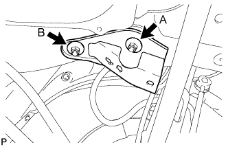
| 4. INSTALL REAR SUSPENSION MEMBER LOWER STOPPER RH |
Install the rear suspension member lower stopper RH with the 2 nuts.
- Torque:
- Nut A:
- 55 N*m{561 kgf*cm, 41 ft.*lbf}
- Nut B:
- 38 N*m{388 kgf*cm, 28 ft.*lbf}
| 5. TEMPORARILY TIGHTEN REAR NO. 1 SUSPENSION ARM LH |
Connect the rear No.1 suspension arm (outer side) to the rear axle carrier with the bolt and nut and temporarily tighten the bolt and nut.
- NOTICE:
- When temporarily tightening the bolt, keep the nut from rotating.
- HINT:
- Insert the bolt from the front of the vehicle and temporarily install the bolt.
| 6. TEMPORARILY TIGHTEN REAR NO. 1 SUSPENSION ARM RH |
- HINT:
- Temporarily tighten the RH side using the same procedures as for the LH side.
| 7. TEMPORARILY TIGHTEN REAR NO. 2 SUSPENSION ARM LH |
Connect the rear No. 2 suspension arm (outer side) to the rear axle carrier with the bolt and nut and temporarily tighten the bolt.
- NOTICE:
- When temporarily tightening the bolt, keep the nut from rotating.
- HINT:
- Insert the bolt from the rear of the vehicle and temporarily install the bolt.
| 8. TEMPORARILY TIGHTEN REAR NO. 2 SUSPENSION ARM RH |
- HINT:
- Temporarily tighten the RH side using the same procedures as for the LH side.
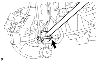
| 9. TEMPORARILY TIGHTEN REAR STRUT ROD |
Connect the strut rod assembly rear to the axle carrier with the bolt and nut and temporarily tighten the bolt.
- NOTICE:
- When temporarily tightening the bolt, keep the nut from rotating.
- HINT:
- Insert the bolt from the inside of the vehicle and temporarily install the bolt.
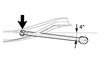
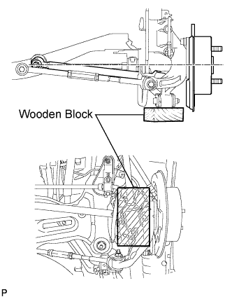
Jack up the rear axle carrier, placing a wooden block to avoid damage. Apply load to the suspension so that the installed bolt of the rear No. 1 suspension arm (inner side) is horizontally aligned with the center of the rear axle hub.
| 11. FULLY TIGHTEN REAR NO. 1 SUSPENSION ARM LH |
Fully tighten the bolt.
- Torque:
- 100 N*m{1,020 kgf*cm, 74 ft.*lbf}
| 12. FULLY TIGHTEN REAR NO. 1 SUSPENSION ARM RH |
- HINT:
- Fully tighten the RH side using the same procedures as for the LH side.
| 13. FULLY TIGHTEN REAR NO. 2 SUSPENSION ARM LH |
Fully tighten the bolt.
- Torque:
- 100 N*m{1,020 kgf*cm, 74 ft.*lbf}
| 14. FULLY TIGHTEN REAR NO. 2 SUSPENSION ARM RH |
- HINT:
- Fully tighten the RH side using the same procedures as for the LH side.
| 15. FULLY TIGHTEN REAR STRUT ROD |
Fully tighten the bolt.
- Torque:
- 113 N*m{1,152 kgf*cm, 83 ft.*lbf}
Fully tighten the bolt.
- Torque:
- 113 N*m{1,152 kgf*cm, 83 ft.*lbf}
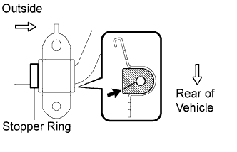
| 16. INSTALL REAR STABILIZER BUSHING |
Install the 2 rear stabilizer bushings to the outside of the stopper ring on the stabilizer bar.
| 17. INSTALL REAR STABILIZER BAR NO. 2 BRACKET |
Install the rear stabilizer bar No. 2 bracket.
| 18. INSTALL REAR STABILIZER BAR NO. 1 BRACKET |
Install the rear stabilizer bar No. 1 bracket.
| 19. INSTALL REAR STABILIZER BAR |
| 20. INSTALL REAR STABILIZER LINK ASSEMBLY LH |
Install the rear stabilizer link assembly LH with the 2 nuts.
- Torque:
- 39 N*m{398 kgf*cm, 29 ft.*lbf}
- HINT:
- If the ball joint turns together with the nut, use a hexagon wrench (5 mm) to hold the stud.
| 21. INSTALL REAR STABILIZER LINK ASSEMBLY RH |
Install the rear stabilizer link assembly RH with the 2 nuts.
- Torque:
- 39 N*m{398 kgf*cm, 29 ft.*lbf}
- HINT:
- If the ball joint turns together with the nut, use a hexagon wrench (5 mm) to hold the stud.
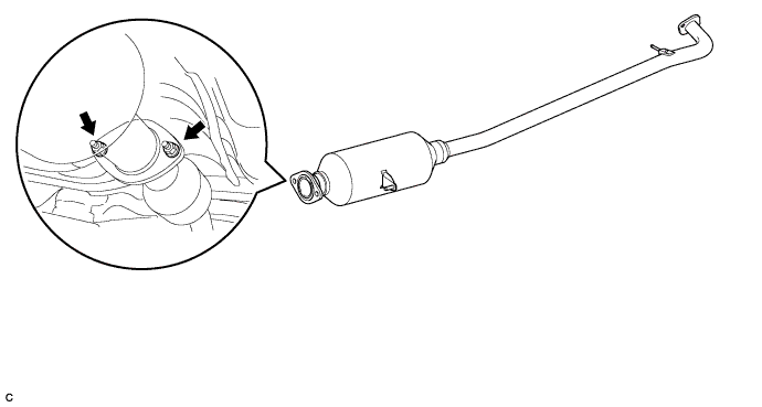
| 22. INSTALL CENTER EXHAUST PIPE ASSEMBLY (for 2AZ-FE) |
Install a new gasket onto the front exhaust pipe.
Install the center exhaust pipe assembly with the 2 bolts and 2 nuts.
- Torque:
- 43 N*m{438 kgf*cm, 32 ft.*lbf}
| 23. INSTALL CENTER EXHAUST PIPE ASSEMBLY (for 2GR-FE) |
Install a new gasket to the exhaust center pipe assembly.
Install the exhaust center pipe to the exhaust front pipe with the 2 nuts and 2 bolts.
- Torque:
- 56 N*m{571 kgf*cm, 41 ft.*lbf}
| 24. INSTALL TAIL EXHAUST PIPE ASSEMBLY (for 2GR-FE) |
Install 2 new gaskets to the exhaust tail pipes.
Install the 2 exhaust tail pipes with the 4 nuts.
- Torque:
- 43 N*m{438 kgf*cm, 32 ft.*lbf}
- Torque:
- 103 N*m{1,050 kgf*cm, 76 ft.*lbf}
| 26. CHECK FOR EXHAUST GAS LEAKAGE |
If gas is leaking, tighten the areas necessary to stop the leak. Replace the damaged parts as necessary.
| 27. INSPECT AND ADJUST REAR WHEEL ALIGNMENT |
(CAMRY_ACV40 RM0000011DQ02FX.html)