Front Wheel Alignment -- Adjustment |
- NOTICE:
- For vehicles equipped with VSC, if the wheel alignment has been adjusted, and if suspension or underbody components have been removed/installed or replaced, be sure to perform the following initialization procedure in order for the system to function normally
- Disconnect the negative battery terminal for more than 2 seconds.
- Reconnect the negative battery terminal.
- Perform zero point calibration of the yaw rate and acceleration sensor and test mode inspection.
- HINT:
| 1. INSPECT TIRES |
Check the tires for wear and proper inflation pressure.
- Cold tire inflation pressure:
Tire size Front kPa (kgf*cm2, psi) Rear kPa (kgf*cm2, psi) 215/60R16 95V 4 passengers or less 250 (2.5, 36)*1, 230 (2.3, 33)*2, 210 (2.1, 31)*3 250 (2.5, 36)*1, 230 (2.3, 33)*2, 210 (2.1, 31)*3 5 passengers 270 (2.8, 39)*1, 250 (2.5, 36)*2, 220 (2.2, 32)*3 270 (2.8, 39)*1, 250 (2.5, 36)*2, 220 (2.2, 32)*3
*2: For driving at 160 km/h (100 mph) to 210 km/h (131 mph).
*3: For driving at under 160 km/h (100 mph).
Using a dial indicator, check the runout of the tires.
- Tire runout:
- 1.4 mm (0.055 in.) or less
 |
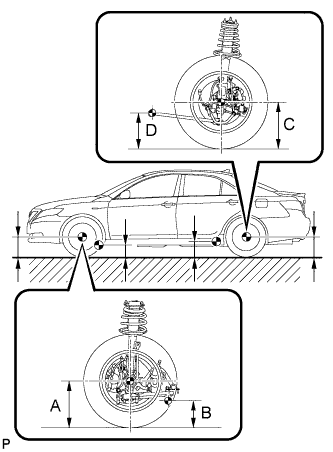
| 2. MEASURE VEHICLE HEIGHT |
Bounce the vehicle up and down at the corners to stabilize the suspension. Inspect the vehicle height.
- Vehicle height:
Engine Transaxle Front A - B Rear C - D 2AZ-FE Automatic 115 mm (4.53 in.) 38 mm (1.50 in.) 2AZ-FE Manual 116 mm (4.57 in.) 39 mm (1.53 in.) 2GR-FE Automatic 117 mm (4.61 in.) 42 mm (1.65 in.)
- Measuring points:
- A:
- Ground clearance of front wheel center
- B:
- Ground clearance of lower suspension arm No. 2 bushing set bolt center
- C:
- Ground clearance of rear wheel center
- D:
- Ground clearance of strut rod set bolt center
- NOTICE:
- Before inspecting the wheel alignment, adjust the vehicle height to the specified value.
- Be sure to perform measurement on a level surface.
- If it is necessary to go under the vehicle for measurement, confirm that the parking brake is applied and the vehicle is secured with chocks.
 |
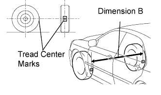
| 3. INSPECT TOE-IN |
Bounce the vehicle up and down at the corners to stabilize the suspension.
Release the parking brake and move the shift lever to the neutral position.
Push the vehicle straight ahead approximately 5 m (16.4 ft). (*1)
Put tread center marks on the rearmost points of the front wheels and measure the distance between the marks (dimension B).
 |
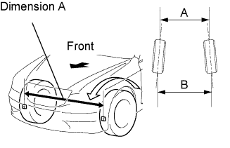
Slowly push the vehicle straight ahead to cause the front wheels to rotate 180° using the front tire valve as a reference point.
- HINT:
- Do not allow the wheels to rotate more than 180°. If the wheels rotate more than 180°, perform the procedure from *1 again.
Measure the distance between the tread center marks on the front side of the wheels.
- Toe-in:
Toe-in
(total)- A - B: 0 +/- 2 mm (0 +/- 0.08 in.)
- HINT:
- If toe-in is not within the specified range, adjust it at the rack ends.
 |
| 4. ADJUST TOE-IN |
Measure the thread lengths of the right and left rack ends.
- Standard:
- Difference in thread length between the right and left rack ends is 1.5 mm (0.059 in.) or less.
 |
Remove the rack boot set clips.
Loosen the tie rod end lock nuts.
Adjust the rack ends if the difference in thread length between the right and left rack ends is not within the specified range.
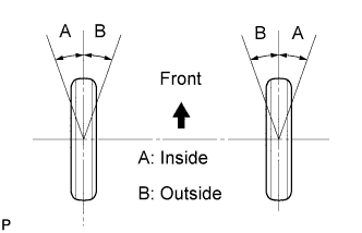
Extend the shorter rack end if the measured toe-in deviates toward the outside.
Shorten the longer rack end if the measured toe-in deviates toward the inside.
Turn the right and left rack ends by equal amounts to adjust the toe-in.
- HINT:
- Try to adjust the toe-in to the center of the specified range.
Make sure that the lengths of the right and left rack ends are the same.
Tighten the tie rod end lock nuts.
- Torque:
- 74 N*m{755 kgf*cm, 55 ft.*lbf}
- NOTICE:
- Temporarily tighten the lock nut while holding the hexagonal part of the steering rack end so that the lock nut and the steering rack end do not turn together. Hold the width across flats on the tie rod end and tighten the lock nut.
Place the boots on the seats and install the clips.
- HINT:
- Make sure that the boots are not twisted.
| 5. INSPECT WHEEL ANGLE |
Put tread center marks on the rearmost points of the turning radius gauge.
Turn the steering wheel fully to the left and right and measure the turning angle.
- Wheel turning angle:
Inside wheel Outside wheel reference 38°42' +/- 2°(38.70°+/- 2°) 33°46' (33.77°)
 |
| 6. INSPECT CAMBER, CASTER AND STEERING AXIS INCLINATION |
Put the front wheel on the center of the alignment tester.
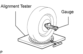 |
Remove the center ornament.
Set the camber-caster-king pin gauge and attachment at the center of the axle hub or drive shaft.
Inspect the camber, caster and steering axis inclination.
- Camber:
Camber Right-left difference -0°30' +/- 45' (-0.50°+/- 0.75°) 45' (0.75°) or less
- Caster:
Caster Right-left difference 2°40' +/- 45' (2.67°+/- 0.75°) 45' (0.75°) or less
- Steering axis inclination:
Steering axis inclination Right-left difference 12°00' +/- 45' (12.00°+/- 0.75°) 45' (0.75°) or less
- NOTICE:
- Perform this inspection while the vehicle is unloaded.
- The maximum tolerance of the right and left difference for the camber and caster is 45' (0.75°) or less.
Remove the camber-caster-king pin gauge and attachment.
Install the center ornament.
If the caster and steering axis inclination are not within the specified range after the camber has been correctly adjusted, recheck the suspension parts for damage and/or wear.
| 7. ADJUST CAMBER |
- NOTICE:
- Inspect toe-in after the camber has been adjusted.
Remove the front wheel.
Remove the 2 nuts on the lower side of the front shock absorber.
- NOTICE:
- Keep the bolts inserted.
 |
Clean the installation surfaces of the front shock absorber and the steering knuckle.
Temporarily install the 2 nuts (Step A).
Fully push or pull the front axle hub in the direction of the required adjustment (Step B).
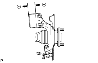 |
Tighten the nuts.
- Torque:
- 210 N*m{2,141 kgf*cm, 155 ft.*lbf}
- NOTICE:
- Keep the bolts from rotating and tighten the nuts when installing the nuts.
Install the front wheel.
- Torque:
- 103 N*m{1,050 kgf*cm, 76 ft.*lbf}
Check the camber.
If the measured value is not within the specification, calculate the required adjustment amount using the formula below.
Camber adjustment amount = Specified range center - measured value
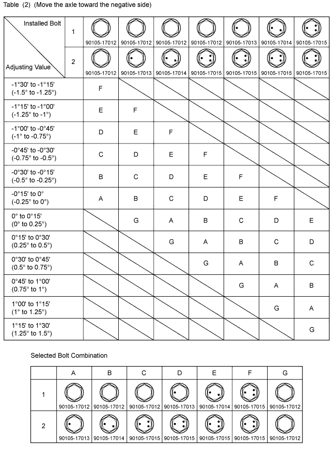
Check the combination of installed bolts. Select appropriate bolts from the table below to adjust the camber to the specified values.- HINT:
- Try to adjust the camber to the center of the specified values.
The body and suspension may be damaged if the camber is not correctly adjusted according to the above table.Move the axle toward (+) in step (B) Move the axle toward (-) in step (B) Refer to table (1) (Move the axle toward positive side) Refer to table (2) (Move the axle toward negative side) - NOTICE:
- Replace the nut with a new one when replacing the bolt.
   |
Repeat the steps mentioned above. In step (A), replace 1 or 2 selected bolts.
- HINT:
- Replace one bolt at a time when replacing 2 bolts.
| 8. FRONT WHEELS FACING STRAIGHT AHEAD |
| 9. DISCONNECT CABLE FROM NEGATIVE BATTERY TERMINAL (w/ VSC) |
- NOTICE:
- Disconnect the cable from the negative battery terminal for more than 2 seconds.
| 10. CONNECT CABLE TO NEGATIVE BATTERY TERMINAL (w/ VSC) |
| 11. PERFORM YAW RATE SENSOR ZERO POINT CALIBRATION (w/ VSC) |
| 12. CHECK STEERING ANGEL SENSOR ZERO POINT (w/ VSC) |