Body Electrical. Camry. Acv40 Gsv40
Navigation. Camry. Acv40 Gsv40
Navigation System -- Terminals Of Ecu |
| NAVIGATION RECEIVER ASSEMBLY |
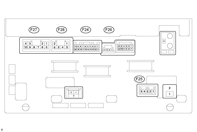
| Terminal No. (Symbol) | Wiring Color | Terminal Description | Condition | Specified Condition |
| F27-1 (FR+) - F27-7 (GND) | LG - BR | Sound signal (Front right) | Audio system playing | A waveform synchronized with sounds is output |
| F27-2 (FL+) - F27-7 (GND) | P - BR | Sound signal (Front left) | Audio system playing | A waveform synchronized with sounds is output |
| F27-3 (ACC) - F27-7 (GND) | GR - BR | Accessory (ON) | Ignition switch off → ACC or ON | Below 1 V → 11 to 14 V |
| F27-4 (B) - F27-7 (GND) | L-Y - BR | Battery | Always | 11 to 14 V |
| F27-5 (FR-) - F27-7 (GND) | L - BR | Sound signal (Front right) | Audio system playing | A waveform synchronized with sounds is output |
| F27-6 (FL-) - F27-7 (GND) | V - BR | Sound signal (Front left) | Audio system playing | A waveform synchronized with sounds is output |
| F27-7 (GND) - Body ground | BR - Body ground | Ground | Always | Below 1 Ω |
| F24-6 (SWG) - F27-7 (GND) | P - BR | Steering pad switch signal | Always | Below 1 V |
| F27-10 (ILL+) - F27-7 (GND) | G - BR | Illumination signal | Ignition switch ON Light control switch off → tail or on | Below 1 V → 11 to 14 V |
| F24-7 (SW1) - F24-6 (SWG) | BE - P | Steering pad switch signal | No switch pushed → MODE switch pushed → on hook switch pushed → off hook switch pushed → voice switch pushed | 4.44 to 5.43 V → 0.45 to 0.65 V → 1.19 to 1.49 V → 2.09 to 2.54 V → 3.2 to 3.88 V |
| F24-8 (SW2) - F24-6 (SWG) | Y - P | Steering pad switch signal | No switch pushed → seek+ switch pushed → seek- switch pushed → vol+ switch pushed → vol- switch pushed | 4.44 to 5.43 V → 0.45 to 0.65 V → 1.19 to 1.49 V → 2.09 to 2.54 V → 3.2 to 3.88 V |
| F24-15 (ARI) - F24-16 (ASGN) | B - W | Sound signal (Right) | External device playing (When stereo jack used) | A waveform synchronized with sounds is output |
| F24-16 (ASGN) - F27-7 (GND) | W - BR | Sound signal ground | Always | Below 1 V |
| F24-17 (ALI) - F24-16 (ASGN) | R - W | Sound signal (Left) | External device playing (When stereo jack used) | A waveform synchronized with sounds is output |
| F24-18 (AGND) - Body ground | Shield - Body ground | Shield ground | Always | Below 1 V |
| F24-19 (AUXI) - F27-7 (GND) | G - BR | External device connection detection signal | External device connected | Below 1 V |
| F25-2 (IG) - F27-7 (GND) | B - BR | Power source (IG) | Ignition switch ON | 11 to 14 V |
| Ignition switch off | Below 1 V | |||
| F25-3 (SPD) - F27-7 (GND) | V - BR | Speed signal from combination meter assembly | See "Vehicle Signal Check Mode" (CAMRY_ACV40 RM000003SKF042X.html) | - |
| F25-5 (REV) - F27-7 (GND) | R - BR | Reverse signal | See "Vehicle Signal Check Mode" (CAMRY_ACV40 RM000003SKF042X.html) | - |
| F24-3 (SNS2) - F27-7 (GND) | LG - BR | Microphone connection detection signal | Always | Below 1 V |
| F24-5 (MACC) - F27-7 (GND) | B - BR | Telephone microphone assembly power supply | Ignition switch off → ON | Below 1 V → 4.75 to 5.25 V |
| F24-14 (SGND) - Body ground | Shield - Body ground | Shield ground | Always | Below 1 V |
| F24-4 (MIN+) - F27-7 (GND) | W - BR | Microphone voice signal | See "Microphone&Voice Recognition Check" (CAMRY_ACV40 RM000003SKF042X.html) | - |
| F24-13 (MIN-) - Body ground | R - Body ground | Microphone voice signal | See "Microphone&Voice Recognition Check" (CAMRY_ACV40 RM000003SKF042X.html) | - |
| F24-11 (V-) - Body ground | W - Body ground | Ground | Always | Below 1 V |
| F24-1 (V+) - F27-7 (GND) | R - BR | Television camera image signal | Ignition switch ON Shift lever in R Under normal conditions | Pulse generation (Refer to waveform 1) |
| Ignition switch ON Shift lever in R Camera lens covered, blacking out screen | Pulse generation (Refer to waveform 2) | |||
| F24-12 (CGND) - F27-7 (GND) | Shield - BR | Shield ground | Always | Below 1 V |
| F24-2 (CA+) - F27-7 (GND) | B - BR | Television camera power supply | Ignition switch ON Shift lever in R | 5.8 to 6.2 V |
| F28-1 (RR+) - F27-7 (GND) | R - BR | Sound signal (Rear right) | Audio system playing | A waveform synchronized with sounds is output |
| F28-2 (RL+) - F27-7 (GND) | B - BR | Sound signal (Rear left) | Audio system playing | A waveform synchronized with sounds is output |
| F28-3 (RR-) - F27-7 (GND) | W - BR | Sound signal (Rear right) | Audio system playing | A waveform synchronized with sounds is output |
| F28-6 (RL-) - F27-7 (GND) | Y - BR | Sound signal (Rear left) | Audio system playing | A waveform synchronized with sounds is output |
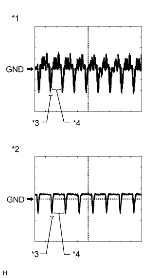
Reference (Oscilloscope waveform):
Waveform 1 (under normal conditions)
Item Content Measurement terminal F24-1 (V+) - F27-7 (GND) Measurement setting 200 mV/DIV., 50 μsec./DIV. Condition Ignition switch ON, shift lever in R - HINT:
- The video waveform changes according to the image that the television camera assembly projects.
Waveform 2 (camera lens is covered, blacking out the screen)
Item Content Measurement terminal F24-1 (V+) - F27-7 (GND) Measurement setting 200 mV/DIV., 50 μsec./DIV. Condition Ignition switch ON, shift lever in R - HINT:
- The video waveform changes according to the image from the television camera assembly.
Text in Illustration *1 Waveform 1 (under normal conditions) *2 Waveform 2 (camera lens is covered, blacking out the screen) *3 Synchronization Signal *4 Video Waveform
 |