Sfi System Fuel Injector Circuit
DESCRIPTION
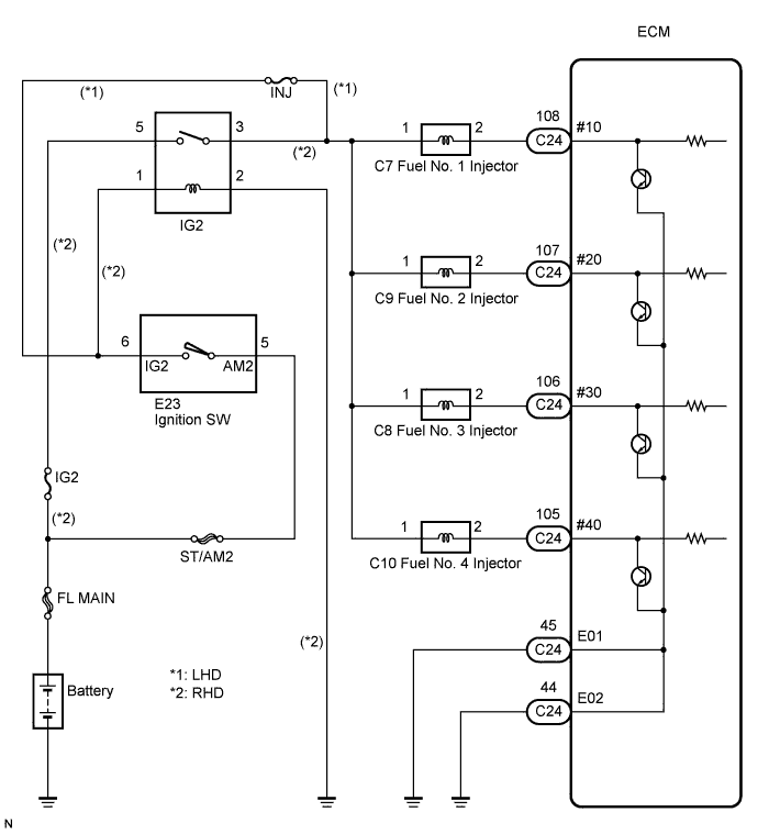
WIRING DIAGRAM
INSPECTION PROCEDURE
INSPECT ECM (#10, #20, #30, #40 VOLTAGE)
INSPECT FUEL INJECTOR (RESISTANCE)
CHECK HARNESS AND CONNECTOR
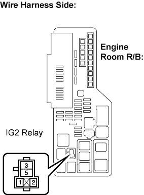
INSPECT IGNITION RELAY NO. 2
CHECK HARNESS AND CONNECTOR (IG2 RELAY - BODY GROUND)
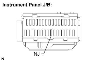
INSPECT FUSE (INJ FUSE)
INSPECT IGNITION SWITCH
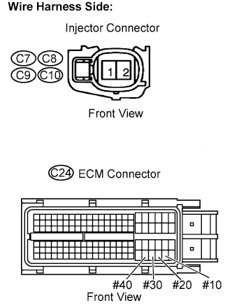
CHECK HARNESS AND CONNECTOR (INJECTOR - ECM)
CHECK HARNESS AND CONNECTOR (ECM - BODY GROUND)
INSPECT FUEL INJECTOR (FUEL INJECTION VOLUME)
SFI SYSTEM - Fuel Injector Circuit |
DESCRIPTION
The fuel injectors are located on the intake manifold. They inject fuel into the cylinders based on the signals from the ECM.
WIRING DIAGRAM
INSPECTION PROCEDURE
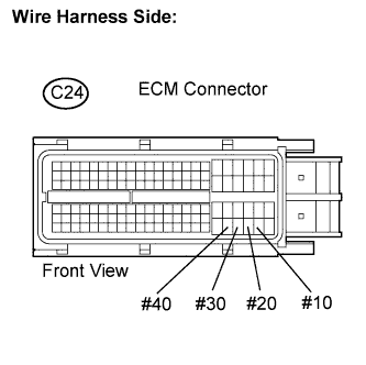
| 1.INSPECT ECM (#10, #20, #30, #40 VOLTAGE) |
Disconnect the C24 ECM connector.
Turn the ignition switch to the ON position.
Measure the voltage between the terminals of the ECM connector.
- Standard voltage:
Tester Connection
| Specified Condition
|
#10 (C24-108) - Body ground
| 9 to 14 V
|
#20 (C24-107) - Body ground
|
#30 (C24-106) - Body ground
|
#40 (C24-105) - Body ground
|
Reconnect the ECM connector.
| 2.INSPECT FUEL INJECTOR (RESISTANCE) |
Inspect the fuel injector (CAMRY_ACV40 RM000000YCT003X_01_0001.html).
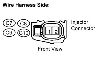
| 3.CHECK HARNESS AND CONNECTOR |
Disconnect the C7 to C10 injector connectors.
Turn the ignition switch to the ON position.
Measure the voltage.
- Standard voltage:
Cylinder
| Tester Connection
| Specified Condition
|
No. 1
| C7-1 - Body ground
| 11 to 14 V
|
No. 2
| C9-1 - Body ground
|
No. 3
| C8-1 - Body ground
|
No. 4
| C10-1 - Body ground
|
- Result:
Result
| Proceed to
|
NG (RHD)
| A
|
NG (LHD)
| B
|
OK
| C
|
Reconnect the injector connectors.
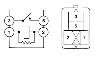
| 4.INSPECT IGNITION RELAY NO. 2 |
Remove the IG2 relay from the engine room R/B.
Measure the resistance between the terminals.
- Standard resistance:
Tester Connection
| Specified Condition
|
3 - 5
| 10 kΩ or higher
|
Below 1 Ω
(Apply battery voltage between terminals 1 and 2)
|
Reinstall the IG2 relay.
| | REPLACE IGNITION RELAY NO. 2 |
|
|
| 5.CHECK HARNESS AND CONNECTOR (IG2 RELAY - BODY GROUND) |
Remove the IG2 relay from the engine room R/B.
Measure the resistance between the terminals.
- Standard resistance:
Tester Connection
| Specified Condition
|
IG2 relay terminal 2 - Body ground
| Below 1 Ω
|
Reinstall the IG2 relay.
| NG |
|
|
|
| REPAIR OR REPLACE HARNESS OR CONNECTOR |
|
| 6.INSPECT FUSE (INJ FUSE) |
Remove the INJ fuse from the instrument panel J/B.
Measure the fuse resistance.
- Standard resistance:
- Below 1 Ω
Reinstall the fuse.
| 7.INSPECT IGNITION SWITCH |
Disconnect the E23 ignition switch connector.
Measure the resistance between the terminals.
- Standard resistance:
Tester Connection
| Ignition Switch Position
| Specified Condition
|
All Terminals
| LOCK
| 10 kΩ or higher
|
2 - 4
| ACC
| Below 1 Ω
|
1 - 2 - 4, 5 - 6
| ON
|
1 - 3 - 4, 5 - 6 - 7
| START
|
Reconnect the ignition switch connector.
| OK |
|
|
|
| REPAIR OR REPLACE HARNESS OR CONNECTOR (BATTERY - FUEL INJECTOR) |
|
| 8.CHECK HARNESS AND CONNECTOR (INJECTOR - ECM) |
Disconnect the C7 to C10 injector connectors.
Disconnect the C24 ECM connector.
Measure the resistance between the injector and the ECM connector terminals.
- Standard resistance:
Cylinder
| Tester Connection
| Specified Condition
|
No. 1
| C7-2 or #10 (C24-108) - Body ground
| 10 kΩ or higher
|
C7-2 - #10 (C24-108)
| Below 1 Ω
|
No. 2
| C9-2 or #20 (C24-107) - Body ground
| 10 kΩ or higher
|
C9-2 - #20 (C24-107)
| Below 1 Ω
|
No. 3
| C8-2 or #30 (C24-106) - Body ground
| 10 kΩ or higher
|
C8-2 - #30 (C24-106)
| Below 1 Ω
|
No. 4
| C10-2 or #40 (C24-105) - Body ground
| 10 kΩ or higher
|
C10-2 - #40 (C24-105)
| Below 1 Ω
|
Reconnect the injector connectors.
Reconnect the ECM connector.
| | REPAIR OR REPLACE HARNESS OR CONNECTOR |
|
|
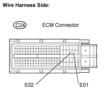
| 9.CHECK HARNESS AND CONNECTOR (ECM - BODY GROUND) |
Disconnect the C24 ECM connector.
Measure the resistance.
- Standard resistance:
Tester Connection
| Specified Condition
|
E01 (C24-45) - Body ground
| Below 1 Ω
|
E02 (C24-44) - Body ground
| Below 1 Ω
|
Reconnect the ECM connector.
| | REPAIR OR REPLACE HARNESS OR CONNECTOR |
|
|
| 10.INSPECT FUEL INJECTOR (FUEL INJECTION VOLUME) |
Inspect the fuel injector (CAMRY_ACV40 RM000000YCT003X_01_0001.html).
| OK |
|
|
|
| PROCEED TO NEXT CIRCUIT INSPECTION SHOWN IN PROBLEM SYMPTOMS TABLE |
|