Cruise Control System Clutch Switch Circuit
DESCRIPTION
WIRING DIAGRAM
INSPECTION PROCEDURE
INSPECT ECM
INSPECT CLUTCH SWITCH
CHECK HARNESS AND CONNECTOR
CRUISE CONTROL SYSTEM - Clutch Switch Circuit |
DESCRIPTION
Clutch switch circuit inspection is necessary for M/T vehicles.When the clutch pedal is released, the ECM receives positive (+) battery voltage through the ECU IG No. 2 fuse. While depressing the clutch pedal, the clutch switch sends a signal to terminal D of the ECM. The ECM cancels cruise control drive when terminal D receives the signal.
WIRING DIAGRAM
INSPECTION PROCEDURE
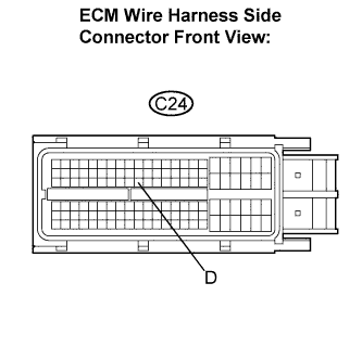
Disconnect the C24 connector from the ECM.
Turn the ignition switch to the ON position.
Measure the voltage according to the value(s) in the table below.
- Standard voltage:
Tester Connection
| Condition
| Specified Condition
|
C24-56 (D) - Body ground
| Clutch pedal depressed
| Below 1 V
|
Clutch pedal released
| 10 to 14 V
|
| | PROCEED TO NEXT CIRCUIT INSPECTION SHOWN IN PROBLEM SYMPTOMS TABLE |
|
|
Turn the ignition switch off.
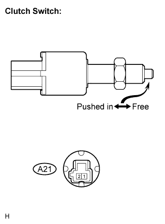
Disconnect the A21 connector from the clutch switch.
Remove the clutch switch. (CAMRY_ACV40 RM000001QPP00AX.html)
Measure the resistance according to the value(s) in the table below.
- Standard resistance:
Tester Connection
| Condition
| Specified Condition
|
1 - 2
| Switch pin free (Clutch pedal depressed)
| 10 kΩ or higher
|
Switch pin pushed in (Clutch pedal released)
| Below 1 Ω
|
| 3.CHECK HARNESS AND CONNECTOR |
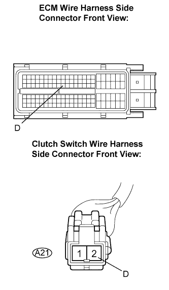
Measure the resistance according to the value(s) in the table below.
- Standard resistance:
Tester Connection
| Condition
| Specified Condition
|
C24-56 (D) - A21-2
| Always
| Below 1 Ω
|
C24-56 (D) - Body ground
| Always
| 10 kΩ or higher
|
| | REPAIR OR REPLACE HARNESS OR CONNECTOR (ECM - CLUTCH SWITCH) |
|
|
| OK |
|
|
|
| REPAIR OR REPLACE HARNESS OR CONNECTOR (BATTERY - CLUTCH SWITCH) |
|