Automatic Transaxle Assembly Removal
DISCHARGE FUEL SYSTEM PRESSURE
DISCONNECT CABLE FROM NEGATIVE BATTERY TERMINAL
PLACE FRONT WHEELS FACING STRAIGHT AHEAD
REMOVE FRONT WHEELS
REMOVE ENGINE UNDER COVER LH
REMOVE ENGINE UNDER COVER RH
REMOVE FRONT FENDER APRON SEAL RH
DRAIN ENGINE OIL
DRAIN ENGINE COOLANT
DRAIN AUTOMATIC TRANSAXLE FLUID
REMOVE WINDSHIELD WIPER LINK ASSEMBLY
REMOVE COWL TOP PANEL OUTER SUB-ASSEMBLY
REMOVE NO. 1 ENGINE COVER SUB-ASSEMBLY
REMOVE V-RIBBED BELT
REMOVE AIR CLEANER INLET ASSEMBLY
REMOVE AIR CLEANER CAP SUB-ASSEMBLY
REMOVE AIR CLEANER CASE SUB-ASSEMBLY
REMOVE BATTERY
REMOVE NO. 2 ENGINE MOUNTING STAY RH
REMOVE ENGINE MOVING CONTROL ROD SUB-ASSEMBLY
REMOVE NO. 2 ENGINE MOUNTING BRACKET RH
DISCONNECT NO. 1 VACUUM HOSE CONNECTOR
DISCONNECT RADIATOR HOSE INLET
DISCONNECT RADIATOR HOSE OUTLET
DISCONNECT OIL COOLER INLET HOSE
DISCONNECT OIL COOLER OUTLET HOSE
DISCONNECT HEATER WATER HOSE INLET
DISCONNECT HEATER WATER HOSE OUTLET
REMOVE ECM
DISCONNECT ENGINE WIRE
DISCONNECT TRANSMISSION CONTROL CABLE ASSEMBLY
DISCONNECT NO. 1 OIL RESERVOIR TO PUMP HOSE
DISCONNECT RETURN TUBE SUB-ASSEMBLY
DISCONNECT FUEL TUBE SUB-ASSEMBLY
REMOVE GENERATOR ASSEMBLY
SEPARATE COMPRESSOR AND MAGNETIC CLUTCH
REMOVE FRONT EXHAUST PIPE ASSEMBLY
REMOVE FRONT AXLE HUB NUT LH
REMOVE FRONT AXLE HUB NUT RH
REMOVE FRONT STABILIZER LINK ASSEMBLY LH
REMOVE FRONT STABILIZER LINK ASSEMBLY RH
REMOVE FRONT SPEED SENSOR LH
REMOVE FRONT SPEED SENSOR RH
DISCONNECT TIE ROD ASSEMBLY LH
DISCONNECT TIE ROD ASSEMBLY RH
DISCONNECT FRONT SUSPENSION LOWER NO. 1 ARM LH
DISCONNECT FRONT SUSPENSION LOWER NO. 1 ARM RH
SEPARATE FRONT AXLE ASSEMBLY LH
SEPARATE FRONT AXLE ASSEMBLY RH
REMOVE DRIVE PLATE AND TORQUE CONVERTER CLUTCH SETTING BOLT
SEPARATE STEERING SLIDING YOKE
REMOVE ENGINE ASSEMBLY WITH TRANSAXLE
REMOVE VANE PUMP ASSEMBLY
REMOVE FRONT FRAME ASSEMBLY
REMOVE FRONT DRIVE SHAFT ASSEMBLY LH
REMOVE FRONT DRIVE SHAFT ASSEMBLY RH
REMOVE ENGINE WIRE
REMOVE STARTER ASSEMBLY
REMOVE ENGINE MOUNTING FRONT BRACKET
SEPARATE AUTOMATIC TRANSAXLE ASSEMBLY
REMOVE TORQUE CONVERTER CLUTCH ASSEMBLY
REMOVE SPEEDOMETER DRIVEN HOLE COVER SUB-ASSEMBLY
REMOVE NO. 2 TRANSMISSION CONTROL CABLE BRACKET
REMOVE WIRE HARNESS CLAMP BRACKET
DISCONNECT WIRE HARNESS
DISCONNECT CONNECTORS
REMOVE NO. 1 TRANSMISSION CONTROL CABLE BRACKET
REMOVE TRANSMISSION OIL FILLER TUBE SUB-ASSEMBLY
REMOVE NO. 1 OIL COOLER INLET TUBE
REMOVE NO. 1 OIL COOLER OUTLET TUBE
REMOVE TRANSAXLE CASE UPPER COVER
Automatic Transaxle Assembly -- Removal |
| 1. DISCHARGE FUEL SYSTEM PRESSURE |
- HINT:
- CAMRY_ACV40 RM000000YCO004X.html.
| 2. DISCONNECT CABLE FROM NEGATIVE BATTERY TERMINAL |
| 3. PLACE FRONT WHEELS FACING STRAIGHT AHEAD |
| 5. REMOVE ENGINE UNDER COVER LH |
| 6. REMOVE ENGINE UNDER COVER RH |
| 7. REMOVE FRONT FENDER APRON SEAL RH |
Remove the oil filler cap.
Remove the oil drain plug and drain the oil into a container.
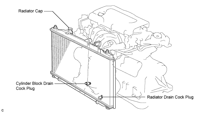
- NOTICE:
- Do not remove the radiator cap sub-assembly while the engine and radiator are still hot. Pressurized, hot engine coolant and steam may be released and cause serious burns.
Remove the radiator cap sub-assembly from the radiator assembly.
Loosen the radiator drain cock plug and cylinder block drain cock plug, then drain the coolant.
- HINT:
- Collect the coolant in a container and dispose of it according to the regulations in your area.
| 10. DRAIN AUTOMATIC TRANSAXLE FLUID |
Using a 6 mm socket hexagon wrench, remove the drain plug and gasket, and drain ATF.
Install a new gasket and the drain plug.
- Torque:
- 49 N*m{500 kgf*cm, 36 ft.*lbf}
| 11. REMOVE WINDSHIELD WIPER LINK ASSEMBLY |
- HINT:
- CAMRY_ACV40 RM0000023QW002X.html.
| 12. REMOVE COWL TOP PANEL OUTER SUB-ASSEMBLY |
Remove the 4 bolts, 4 nuts and outer cowl top panel sub-assembly.
| 13. REMOVE NO. 1 ENGINE COVER SUB-ASSEMBLY |
Remove the 2 nuts and cover.
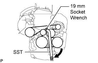
Using SST and 19 mm socket wrench, loosen the V-ribbed belt tensioner arm clockwise, then remove the V-ribbed belt.
- SST
- 09216-42010
- NOTICE:
- Be sure to connect SST and the tools so that they are in line during use.
- When retracting the tensioner, turn it clockwise slowly for 3 seconds or more. Do not apply force rapidly.
- After the tensioner is fully retracted, do not apply force any more than necessary.
| 15. REMOVE AIR CLEANER INLET ASSEMBLY |
Remove the 2 bolts, clamp and air cleaner inlet.
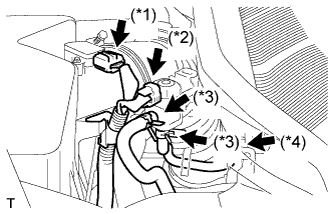
| 16. REMOVE AIR CLEANER CAP SUB-ASSEMBLY |
Disconnect the mass air flow meter connector (*1).
Disconnect the purge VSV connector (*2).
Disconnect the 2 purge VSV vacuum hoses (*3).
Disconnect the purge line hose from the clamp (*4).
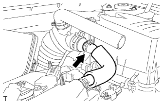
Disconnect the No. 2 ventilation hose from the air cleaner hose.
Lock the No. 1 air cleaner hose clamp, and then disconnect the No. 1 air cleaner hose from the throttle body.
Remove the 2 bolts and air cleaner cap.
Remove the air cleaner filter element from the air cleaner case.
| 17. REMOVE AIR CLEANER CASE SUB-ASSEMBLY |
Disconnect the hose clamp.
Remove the 3 bolts and air cleaner case.
Loosen the bolt and nut, and remove the battery clamp.
Remove the battery and battery tray.
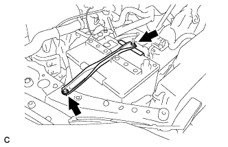
| 19. REMOVE NO. 2 ENGINE MOUNTING STAY RH |
Remove the 2 bolts and No. 2 mounting stay RH.
| 20. REMOVE ENGINE MOVING CONTROL ROD SUB-ASSEMBLY |
Remove the bolt and disconnect the ground cable.
Remove the 3 bolts and the engine moving control rod with bracket.
| 21. REMOVE NO. 2 ENGINE MOUNTING BRACKET RH |
Remove the 3 bolts and No. 2 mounting bracket RH.
| 22. DISCONNECT NO. 1 VACUUM HOSE CONNECTOR |
Remove the clamp and disconnect the vacuum hose connector.
| 23. DISCONNECT RADIATOR HOSE INLET |
Remove the clamp and disconnect the radiator hose inlet.
| 24. DISCONNECT RADIATOR HOSE OUTLET |
Remove the clamp and disconnect the radiator hose outlet.
| 25. DISCONNECT OIL COOLER INLET HOSE |
Disconnect the oil cooler inlet hose from the radiator assembly.
| 26. DISCONNECT OIL COOLER OUTLET HOSE |
Disconnect the oil cooler outlet hose from the radiator assembly.
| 27. DISCONNECT HEATER WATER HOSE INLET |
Disconnect the heater inlet water hose.
| 28. DISCONNECT HEATER WATER HOSE OUTLET |
Disconnect the heater outlet water hose.
- HINT:
- CAMRY_ACV40 RM0000017UO009X.html.
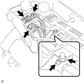
| 30. DISCONNECT ENGINE WIRE |
Disconnect the engine wire from the engine room relay block.
Remove the nut and separate the wire harness.
Using a screwdriver, unlock the engine room R/B. Pull the engine room R/B upward.
Disconnect the engine wire connectors.
Remove the clamp from the bracket.
Remove the 2 bolts and clamp from the body.
| 31. DISCONNECT TRANSMISSION CONTROL CABLE ASSEMBLY |
Remove the nut from the control shaft lever.
Disconnect the transmission control cable assembly from the control shaft lever.
Remove the clip and disconnect the transmission control cable assembly from the No. 1 control cable bracket.
Disconnect the transmission control cable assembly from the control cable clamp.
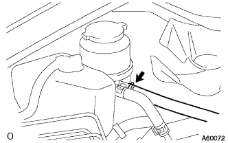
| 32. DISCONNECT NO. 1 OIL RESERVOIR TO PUMP HOSE |
Disconnect the No. 1 oil reservoir to pump hose.
| 33. DISCONNECT RETURN TUBE SUB-ASSEMBLY |
Disconnect the return tube sub-assembly.
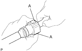
| 34. DISCONNECT FUEL TUBE SUB-ASSEMBLY |
Remove the No. 1 fuel pipe clamp.
Disconnect the connector from the tube while pinching part A with your fingers as shown in the illustration.
- NOTICE:
- Check for contamination in the pipe and around the connector. Clean if necessary and then disconnect the connector.
- Disconnect the connector by hand.
- Do not bend, fold or rotate the nylon tube.
- If the pipe and connector are stuck together, push and pull the connector until it becomes free.
- Put the pipe and connector ends in vinyl bags to prevent damage and contamination.
| 35. REMOVE GENERATOR ASSEMBLY |
Disconnect the generator connector.
Remove the nut and disconnect the wire harness from terminal B.
Remove the bolt and wire harness clamp bracket.
Remove the wire harness clamps.
Remove the 2 bolts and generator assembly.
| 36. SEPARATE COMPRESSOR AND MAGNETIC CLUTCH |
Disconnect the connector.
Remove the 4 bolts and separate the compressor.
- HINT:
- Hang up the hoses instead of detaching them.
| 37. REMOVE FRONT EXHAUST PIPE ASSEMBLY |
Remove the 2 nuts.
Remove the 2 nuts, front exhaust pipe No. 1 support bracket and front exhaust pipe assembly.
Remove the gasket from the exhaust manifold.
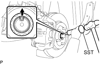
| 38. REMOVE FRONT AXLE HUB NUT LH |
Using SST and a hammer, release the staked part of the front axle hub nut.
- SST
- 09930-00010
- NOTICE:
- Loosen the staked part of the nut completely, otherwise the thread of the drive shaft may be damaged.
While applying the brakes, remove the front axle hub nut.
| 39. REMOVE FRONT AXLE HUB NUT RH |
- HINT:
- Use the same procedures described for the LH side.
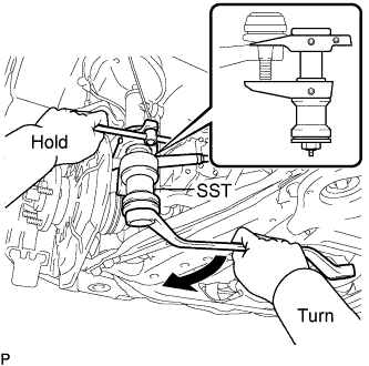
| 40. REMOVE FRONT STABILIZER LINK ASSEMBLY LH |
Remove the nut and separate the front stabilizer link assembly.
- HINT:
- If the ball joint turns together with the nut, use a hexagon wrench (6 mm) to hold the stud.
| 41. REMOVE FRONT STABILIZER LINK ASSEMBLY RH |
- HINT:
- Use the same procedures described for the LH side.
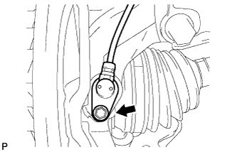
| 42. REMOVE FRONT SPEED SENSOR LH |
Remove the bolt and clip, and separate the speed sensor wire and flexible hose from the shock absorber.
Remove the bolt and separate the speed sensor from the steering knuckle.
- NOTICE:
- Prevent foreign matter from adhering to the speed sensor.
- Be careful not to damage the speed sensor.
| 43. REMOVE FRONT SPEED SENSOR RH |
- HINT:
- Use the same procedures described for the LH side.
| 44. DISCONNECT TIE ROD ASSEMBLY LH |
Remove the cotter pin and nut.
Using SST, separate the tie rod end sub-assembly from the steering knuckle.
- SST
- 09628-00011
- NOTICE:
- Make sure that the string of the SST is securely tied to the vehicle.
- Be careful not to damage the ball joint dust cover.
- Be careful not to damage the steering knuckle.
- Be careful not to damage the front disc brake dust cover.
| 45. DISCONNECT TIE ROD ASSEMBLY RH |
- HINT:
- Use the same procedures described for the LH side.
| 46. DISCONNECT FRONT SUSPENSION LOWER NO. 1 ARM LH |
Remove the bolt and 2 nuts, and separate the front suspension lower No. 1 arm from the lower ball joint.
| 47. DISCONNECT FRONT SUSPENSION LOWER NO. 1 ARM RH |
- HINT:
- Use the same procedures described for the LH side.
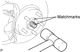
| 48. SEPARATE FRONT AXLE ASSEMBLY LH |
Put matchmarks on the front drive shaft assembly and the axle hub.
Using a plastic hammer, separate the front drive shaft assembly from the front axle assembly.
- NOTICE:
- Be careful not to damage the drive shaft boot and speed sensor rotor.
| 49. SEPARATE FRONT AXLE ASSEMBLY RH |
- HINT:
- Use the same procedures described for the LH side.
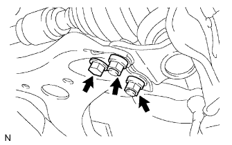
| 50. REMOVE DRIVE PLATE AND TORQUE CONVERTER CLUTCH SETTING BOLT |
Remove the flywheel housing under cover.
Turn the crankshaft to gain access and remove the 6 bolts while holding the crankshaft pulley bolt with a wrench.
- HINT:
- There will be one black colored bolt.
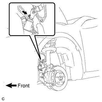
| 51. SEPARATE STEERING SLIDING YOKE |
Secure the steering wheel with the seat belt in order to prevent rotation.
- HINT:
- This operation is useful to prevent damage to the spiral cable.
Remove the bolt and slide the steering sliding yoke.
- NOTICE:
- Do not separate the steering sliding yoke from the power steering link assembly.
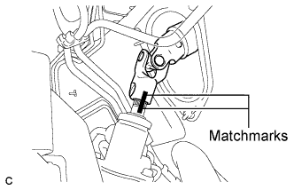
Put matchmarks on the steering sliding yoke and the power steering link assembly.
Separate the steering sliding yoke from the power steering link assembly.
| 52. REMOVE ENGINE ASSEMBLY WITH TRANSAXLE |
Set the engine lifter.
Remove the 4 bolts, 2 nuts and frame side rail plate RH and LH.
Remove the 4 bolts, 2 nuts and front suspension member brace rear RH and LH.
Carefully remove the engine assembly from the vehicle.
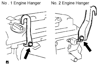
Install the 2 engine hangers as shown in the illustration.
Parts No.:
Parts
| Parts No.
|
No. 1 Engine hanger
| 12281-28010
|
No. 2 Engine hanger
| 12282-28010
|
Bolt
| 91512-61020
|
- Torque:
- 38 N*m{387 kgf*cm, 28 ft.*lbf}
Using a chain block and an engine sling device, hang the engine assembly.
| 53. REMOVE VANE PUMP ASSEMBLY |
Disconnect the oil pressure switch connector.
Loosen the 2 bolts and remove the vane pump from the engine.
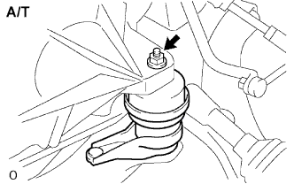
| 54. REMOVE FRONT FRAME ASSEMBLY |
A/T:
Remove the nut from the engine mounting insulator LH.
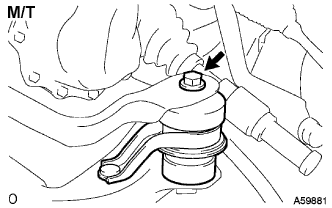
M/T:
Remove the bolt from the engine mounting insulator LH.
Remove the nut from the engine mounting insulator RH.
Remove the bolt from the engine mounting insulator FR.
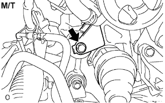
M/T:
Remove the bolt from the engine lateral control rod.
Raise the engine assembly and separate the front frame.
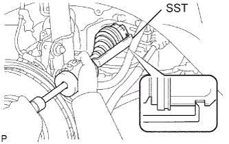
| 55. REMOVE FRONT DRIVE SHAFT ASSEMBLY LH |
Using SST, remove the front drive shaft assembly LH.
- SST
- 09520-01010
09520-24010(09520-32040)
- NOTICE:
- Be careful not to damage the drive shaft dust cover, boot, and oil seal.
- Be careful not to drop the drive shaft assembly.
| 56. REMOVE FRONT DRIVE SHAFT ASSEMBLY RH |
Using a screwdriver, remove the bearing bracket hole snap ring.
Remove the bolt and front drive shaft assembly RH from the drive shaft bearing bracket.
- NOTICE:
- Do not damage the boot and oil seal.
| 58. REMOVE STARTER ASSEMBLY |
Disconnect the terminal 50 connector from the starter assembly.
Remove the nut and disconnect the wire harness from terminal 30.
Remove the 2 bolts and starter assembly.
| 59. REMOVE ENGINE MOUNTING FRONT BRACKET |
Remove the 3 bolts and engine mounting front bracket.
| 60. SEPARATE AUTOMATIC TRANSAXLE ASSEMBLY |
Remove the 5 bolts.
Remove the 4 lower side mounting bolts.
Separate and remove the automatic transaxle.
| 61. REMOVE TORQUE CONVERTER CLUTCH ASSEMBLY |
| 62. REMOVE SPEEDOMETER DRIVEN HOLE COVER SUB-ASSEMBLY |
Remove the bolt and hole cover from the transaxle case.
Remove the O-ring from the hole cover.
| 63. REMOVE NO. 2 TRANSMISSION CONTROL CABLE BRACKET |
Remove the bolt and No. 2 transmission control cable bracket.
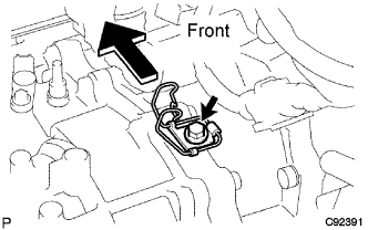
| 64. REMOVE WIRE HARNESS CLAMP BRACKET |
Disconnect the wire harnesses from the 2 brackets.
Remove the 2 bolts and 2 clamps.
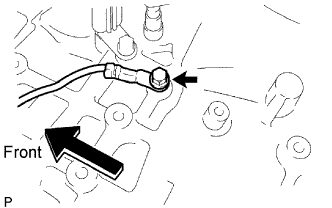
| 65. DISCONNECT WIRE HARNESS |
Remove the bolt and disconnect the wire harness.
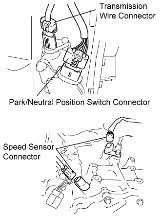
| 66. DISCONNECT CONNECTORS |
Disconnect the transmission wire connector.
Disconnect the park/neutral position switch connector.
Disconnect the 2 speed sensor connectors.
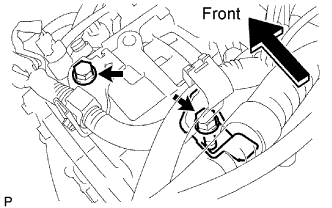
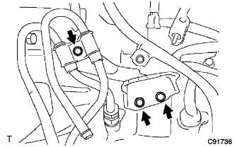
| 67. REMOVE NO. 1 TRANSMISSION CONTROL CABLE BRACKET |
Remove the bolt and oil cooler tube clamp.
Remove the 2 bolts and No. 1 transmission control cable bracket.
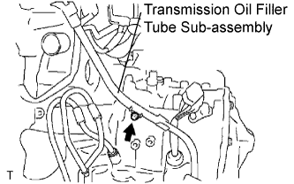
| 68. REMOVE TRANSMISSION OIL FILLER TUBE SUB-ASSEMBLY |
Remove the ATF level gauge.
Remove the bolt and transmission oil filler tube sub-assembly.
Remove the O-ring from the oil filler tube sub-assembly.
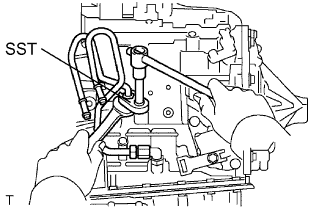
| 69. REMOVE NO. 1 OIL COOLER INLET TUBE |
Using SST and a wrench, disconnect the No. 1 oil cooler inlet tube.
- SST
- 09023-12701
| 70. REMOVE NO. 1 OIL COOLER OUTLET TUBE |
Using SST and a wrench, disconnect the No. 1 oil cooler outlet tube.
- SST
- 09023-12701
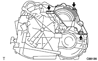
| 71. REMOVE TRANSAXLE CASE UPPER COVER |
Remove the 3 bolts and transaxle case upper cover.