DESCRIPTION
WIRING DIAGRAM
INSPECTION PROCEDURE
CHECK DTC
CHECK CONNECTION OF CONNECTORS
CHECK CONNECTORS
CHECK SEAT POSITION AIRBAG SENSOR CIRCUIT (OPEN)
CHECK SEAT POSITION AIRBAG SENSOR CIRCUIT (SHORT)
CHECK SEAT POSITION AIRBAG SENSOR CIRCUIT (SHORT TO B+)
CHECK SEAT POSITION AIRBAG SENSOR CIRCUIT (SHORT TO GROUND)
CHECK SEAT POSITION AIRBAG SENSOR
REPLACE SEAT POSITION AIRBAG SENSOR
CHECK CENTER AIRBAG SENSOR ASSEMBLY
CHECK WIRE HARNESS (OPEN)
CHECK WIRE HARNESS (SHORT)
CHECK WIRE HARNESS (SHORT TO B+)
CHECK WIRE HARNESS (SHORT TO GROUND)
DTC B1653/35 Seat Position Airbag Sensor Circuit Malfunction |
DESCRIPTION
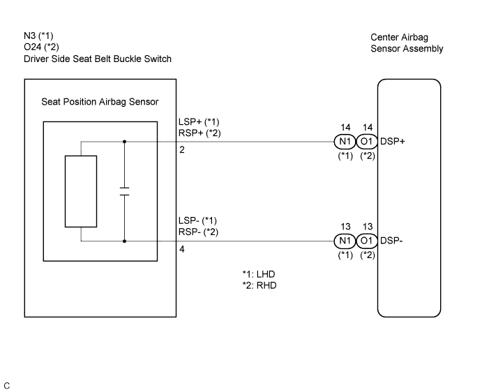
The seat position airbag sensor circuit consists of the center airbag sensor assembly and the seat position airbag sensor.DTC B1653/35 is recorded when a malfunction is detected in the seat position airbag sensor circuit.DTC No.
| DTC Detecting Condition
| Trouble Area
|
B1653/35
| - The center airbag sensor assembly receives a line short circuit signal, an open circuit signal, a short circuit to ground signal or a short circuit to B+ signal in the seat position airbag sensor circuit for 2 seconds.
- Seat position airbag sensor malfunction
- Center airbag sensor assembly malfunction
| - Floor wire (for LHD)
- Floor wire No. 2 (for RHD)
- Front seat inner belt assembly LH
- Seat position airbag sensor
- Center airbag sensor assembly
|
WIRING DIAGRAM
INSPECTION PROCEDURE
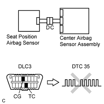
Turn the ignition switch to the ON position, and wait for at least 60 seconds.
Clear the DTCs stored in the memory (CAMRY_ACV40 RM000000XFE07JX.html).
Turn the ignition switch to the LOCK position.
Turn the ignition switch to the ON position, and wait for at least 60 seconds.
Check for DTCs (CAMRY_ACV40 RM000000XFE07JX.html).
- OK:
- DTC B1653/35 is not output.
- HINT:
- Codes other than DTC B1653/35 may be output at this time, but they are not related to this check.
| 2.CHECK CONNECTION OF CONNECTORS |
Turn the ignition switch to the LOCK position.
Disconnect the negative (-) terminal cable from the battery, and wait for at least 90 seconds.
Check that the connectors are properly connected to the center airbag sensor assembly and the seat position airbag sensor.
- OK:
- The connectors are properly connected.
| | CONNECT CONNECTORS, THEN GO TO STEP 1 |
|
|
Disconnect the connectors from the center airbag sensor assembly and the seat position airbag sensor.
Check that the connectors (on the center airbag sensor assembly side and seat position airbag sensor side) are not damaged.
- OK:
- The connectors are not deformed or damaged.
- Result:
Result
| Proceed to
|
OK
| A
|
NG (for LHD)
| B
|
NG (for RHD)
| C
|
| | REPAIR OR REPLACE FLOOR WIRE |
|
|
| | REPAIR OR REPLACE FLOOR WIRE NO. 2 |
|
|
| 4.CHECK SEAT POSITION AIRBAG SENSOR CIRCUIT (OPEN) |
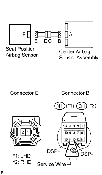
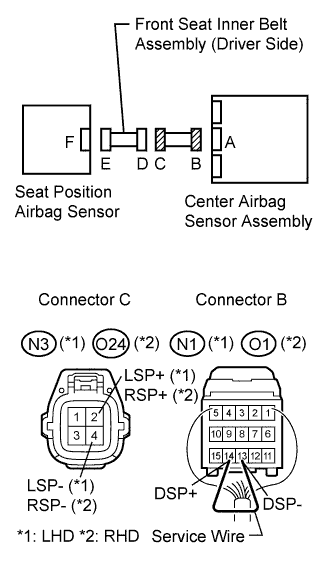
Using a service wire, connect terminals 14 (DSP+) and 13 (DSP-) of connector B.
- NOTICE:
- Do not forcibly insert a service wire into the terminals of the connector when connecting.
Measure the resistance according to the value(s) in the table below.
- Standard resistance:
Tester connection
| Condition
| Specified condition
|
1 - 2
| Always
| Below 1 Ω
|
| 5.CHECK SEAT POSITION AIRBAG SENSOR CIRCUIT (SHORT) |
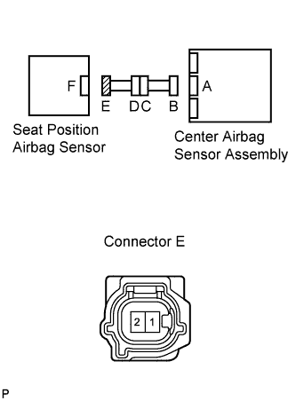
Disconnect the service wire from connector B.
Measure the resistance between the terminals of connector E according to the value(s) in the table below.
- Standard resistance:
Tester connection
| Condition
| Specified condition
|
1 - 2
| Always
| 1 MΩ or higher
|
| 6.CHECK SEAT POSITION AIRBAG SENSOR CIRCUIT (SHORT TO B+) |
Connect the negative (-) terminal cable to the battery, and wait for at least 2 seconds.
Turn the ignition switch to the ON position.
Measure the voltage according to the value(s) in the table below.
- Standard voltage:
Tester connection
| Condition
| Specified condition
|
1 - Body ground
| Ignition switch ON
| Below 1 V
|
2 - Body ground
| Ignition switch ON
| Below 1 V
|
| 7.CHECK SEAT POSITION AIRBAG SENSOR CIRCUIT (SHORT TO GROUND) |
Turn the ignition switch to the LOCK position.
Disconnect the negative (-) terminal cable from the battery, and wait for at least 90 seconds.
Measure the resistance according to the value(s) in the table below.
- Standard resistance:
Tester connection
| Condition
| Specified condition
|
1 - Body ground
| Always
| 1 MΩ or higher
|
2 - Body ground
| Always
| 1 MΩ or higher
|
| 8.CHECK SEAT POSITION AIRBAG SENSOR |
Connect the connectors to the center airbag sensor assembly and the seat position airbag sensor.
Connect the negative (-) terminal cable to the battery, and wait for at least 2 seconds.
Turn the ignition switch to the ON position, and wait for at least 60 seconds.
Clear the DTCs stored in the memory (CAMRY_ACV40 RM000000XFE07JX.html).
Turn the ignition switch to the LOCK position.
Turn the ignition switch to the ON position, and wait for at least 60 seconds.
Check for DTCs (CAMRY_ACV40 RM000000XFE07JX.html).
- OK:
- DTC B1653/35 is not output.
- HINT:
- Codes other than DTC B1653/35 may be output at this time, but they are not related to this check.
| 9.REPLACE SEAT POSITION AIRBAG SENSOR |
Turn the ignition switch to the LOCK position.
Disconnect the negative (-) terminal cable from the battery, and wait for at least 90 seconds.
Replace the seat position airbag sensor (CAMRY_ACV40 RM000000UWJ035X.html).
- HINT:
- Perform inspection using parts from a normal vehicle if possible.
| 10.CHECK CENTER AIRBAG SENSOR ASSEMBLY |
Connect the negative (-) terminal cable to the battery, and wait for at least 2 seconds.
Turn the ignition switch to the ON position, and wait for at least 60 seconds.
Clear the DTCs stored in the memory (CAMRY_ACV40 RM000000XFE07JX.html).
Turn the ignition switch to the LOCK position.
Turn the ignition switch to the ON position, and wait for at least 60 seconds.
Check for DTCs (CAMRY_ACV40 RM000000XFE07JX.html).
- OK:
- DTC B1653/35 is not output.
- HINT:
- Codes other than DTC B1653/35 may be output at this time, but they are not related to this check.
| 11.CHECK WIRE HARNESS (OPEN) |
for LHD:
Disconnect the floor wire connector from the front seat inner belt assembly (driver side).
- HINT:
- The service wire has already been inserted into connector B.
for RHD:
Disconnect the floor wire No. 2 connector from the front seat inner belt assembly (driver side).
- HINT:
- The service wire has already been inserted into connector B.
Measure the resistance according to the value(s) in the table below.
- Standard resistance:
- for LHD:
Tester connection
| Condition
| Specified condition
|
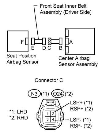
N3-2 (LSP+) - N3-4 (LSP-)
| Always
| Below 1 Ω
|
- for RHD:
Tester connection
| Condition
| Specified condition
|
O24-2 (RSP+) - O24-4 (RSP-)
| Always
| Below 1 Ω
|
- Result:
Result
| Proceed to
|
OK
| A
|
NG (for LHD)
| B
|
NG (for RHD)
| C
|
| | REPAIR OR REPLACE FLOOR WIRE |
|
|
| | REPAIR OR REPLACE FLOOR WIRE NO. 2 |
|
|
| A |
|
|
|
| REPLACE FRONT SEAT INNER BELT ASSEMBLY (DRIVER SIDE) |
|
| 12.CHECK WIRE HARNESS (SHORT) |
for LHD:
Disconnect the floor wire connector from the front seat inner belt assembly (driver side).
for RHD:
Disconnect the floor wire No. 2 connector from the front seat inner belt assembly (driver side).
Measure the resistance according to the value(s) in the table below.
- Standard resistance:
- for LHD:
Tester connection
| Condition
| Specified condition
|
N3-2 (LSP+) - N3-4 (LSP-)
| Always
| 1 MΩ or higher
|
- for RHD:
Tester connection
| Condition
| Specified condition
|
O24-2 (RSP+) - O24-4 (RSP-)
| Always
| 1 MΩ or higher
|
- Result:
Result
| Proceed to
|
OK
| A
|
NG (for LHD)
| B
|
NG (for RHD)
| C
|
| | REPAIR OR REPLACE FLOOR WIRE |
|
|
| | REPAIR OR REPLACE FLOOR WIRE NO. 2 |
|
|
| A |
|
|
|
| REPLACE FRONT SEAT INNER BELT ASSEMBLY (DRIVER SIDE) |
|
| 13.CHECK WIRE HARNESS (SHORT TO B+) |
Turn the ignition switch off.
Disconnect the negative(-) terminal cable from the battery, and wait for at least 90 seconds.
for LHD:
Disconnect the floor wire connector from the front seat inner belt assembly (driver side).
for RHD:
Disconnect the floor wire No. 2 connector from the front seat inner belt assembly (driver side).
Connect the negative (-) terminal cable to the battery, and wait for at least 2 seconds.
Turn the ignition switch on (IG).
Measure the voltage according to the value(s) in the table below.
- Standard voltage:
- for LHD:
Tester connection
| Condition
| Specified condition
|
N3-2 (LSP+) - Body ground
| Ignition switch ON
| Below 1 V
|
N3-4 (LSP-) - Body ground
| Ignition switch ON
| Below 1 V
|
- for RHD:
Tester connection
| Condition
| Specified condition
|
O24-2 (RSP+) - Body ground
| Ignition switch ON
| Below 1 V
|
O24-4 (RSP-) - Body ground
| Ignition switch ON
| Below 1 V
|
- Result:
Result
| Proceed to
|
OK
| A
|
NG (for LHD)
| B
|
NG (for RHD)
| C
|
| | REPAIR OR REPLACE FLOOR WIRE |
|
|
| | REPAIR OR REPLACE FLOOR WIRE NO. 2 |
|
|
| A |
|
|
|
| REPLACE FRONT SEAT INNER BELT ASSEMBLY (DRIVER SIDE) |
|
| 14.CHECK WIRE HARNESS (SHORT TO GROUND) |
Measure the resistance according to the value(s) in the table below.
- Standard resistance:
- for LHD:
Tester connection
| Condition
| Specified condition
|
N3-2 (LSP+) - Body ground
| Always
| 1 MΩ or higher
|
N3-4 (LSP-) - Body ground
| Always
| 1 MΩ or higher
|
- for RHD:
Tester connection
| Condition
| Specified condition
|
O24-2 (RSP+) - Body ground
| Always
| 1 MΩ or higher
|
O24-4 (RSP-) - Body ground
| Always
| 1 MΩ or higher
|
- Result:
Result
| Proceed to
|
OK
| A
|
NG (for LHD)
| B
|
NG (for RHD)
| C
|
| | REPAIR OR REPLACE FLOOR WIRE |
|
|
| | REPAIR OR REPLACE FLOOR WIRE NO. 2 |
|
|
| A |
|
|
|
| REPLACE FRONT SEAT INNER BELT ASSEMBLY (DRIVER SIDE) |
|