Cylinder Head -- Inspection |
| 1. INSPECT CYLINDER HEAD FOR FLATNESS |
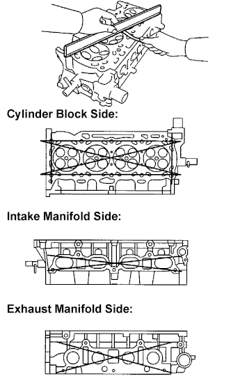
Using a precision straight edge and a feeler gauge, measure the surface contacting the cylinder block and the manifolds for warpage.
- Maximum warpage:
Item Specified Condition Cylinder block side 0.05 mm (0.0020 in.) Intake manifold side 0.08 mm (0.0031 in.) Exhaust manifold side 0.08 mm (0.0031 in.)
 |
| 2. INSPECT CYLINDER HEAD FOR CRACKS |
Using a dye penetrant, check the intake ports, exhaust ports and cylinder surface for cracks.
If cracked, replace the cylinder head.
 |
| 3. INSPECT VALVE SEATS |
Apply a light coat of prussian blue to the valve face.
 |
Lightly press the valve face against the valve seat.
Check the valve face and valve seat according to the following procedure:
If prussian blue appears 360° around the valve face, the valve face is concentric. If not, replace the valve.
If prussian blue appears 360° around the valve seat, the guide and valve face are concentric. If not, resurface the valve seat.
Check that the valve seat contact is in the middle of the valve face with the width between 1.0 to 1.4 mm (Intake side (0.039 to 0.055 in.)).
Check that the valve seat contact is in the middle of the valve face with the width between 1.2 to 1.6 mm (Exhaust side (0.047 to 0.063 in.)).
| 4. REPAIR VALVE SEATS |
- NOTICE:
- Repair the seat while checking the seating position.
- Keep the lip free from foreign matter.
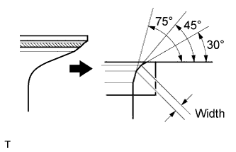
Using a 45° cutter, resurface the valve seat so that the valve seat width is more than the specification.
 |
Using 30° and 75° cutters, correct the valve seat so that the valve contacts the entire circumference of the seat. The contact should be in the center of the valve seat, and the valve seat width should be maintained within the specified range around the entire circumference of the seat.
- Valve Seat Width:
Item Specified Condition Intake Side 1.0 to 1.4 mm (0.039 to 0.055 in.) Exhaust Side 1.2 to 1.6 mm (0.047 to 0.063 in.)
 |
Handrub the valve and valve seat with an abrasive compound.
Check the valve seating position.
| 5. INSPECT CAMSHAFT THRUST CLEARANCE |
Install the camshafts (CAMRY_ACV40 RM000001QBC003X.html).
Using a dial indicator, measure the thrust clearance while moving the camshaft back and forth.
- Standard thrust clearance:
Item Specified Condition Intake 0.040 to 0.095 mm (0.0016 to 0.0037 in.) Exhaust 0.080 to 0.135 mm (0.0032 to 0.0053 in.)
- Maximum thrust clearance:
Item Specified Condition Intake 0.110 mm (0.0043 in.) Exhaust 0.150 mm (0.0059 in.)
 |
| 6. INSPECT CAMSHAFT OIL CLEARANCE |
Clean the bearing caps and camshaft journals.
Place the camshafts on the cylinder head.
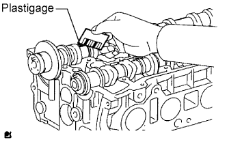
Lay a strip of Plastigage across each of the camshaft journals.
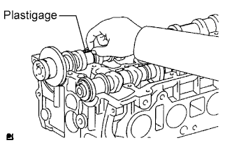 |
Install the bearing caps (CAMRY_ACV40 RM000001QBC003X.html).
- NOTICE:
- Do not turn the camshaft.
Remove the bearing caps (CAMRY_ACV40 RM000001QBF003X.html).
Measure the Plastigage at its widest point.
- Standard oil clearance:
Item Specified Condition Camshaft No. 1 journal bearing mark 1 0.007 to 0.038 mm (0.0003 to 0.0015 in.) Camshaft No. 1 journal bearing mark 2 0.008 to 0.038 mm (0.0003 to 0.0015 in.) Camshaft No. 1 journal bearing mark 3 0.008 to 0.038 mm (0.0003 to 0.0015 in.) Camshaft other journals 0.025 to 0.062 mm (0.0010 to 0.0024 in.) No. 2 camshaft No. 1 journal 0.015 to 0.054 mm (0.0006 to 0.0021 in.) No. 2 camshaft other journals 0.025 to 0.062 mm (0.0010 to 0.0024 in.)
- Maximum oil clearance:
Item Specified Condition Intake 0.070 mm (0.0028 in.) Exhaust 0.100 mm (0.0039 in.)
- NOTICE:
- Completely remove the Plastigage after the inspection.
- If the oil clearance is greater than the maximum, replace the camshaft. If necessary, replace the cylinder head.
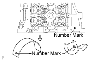
- If the oil clearance on the camshaft No. 1 journal is greater than the maximum, choose a new bearing and install it.
Check the number mark shown in the illustration.
- Cylinder head journal bore diameter:
Mark 1 Mark 2 Mark 3 40.000 to 40.008 mm (1.5748 to 1.5752 in.) 40.009 to 40.017 mm (1.5752 to 1.5755 in.) 40.018 to 40.025 mm (1.5755 to 1.5758 in.)
- Standard bearing center wall thickness:
Mark 1 Mark 2 Mark 3 2.000 to 2.004 mm (0.0787 to 0.0789 in.) 2.005 to 2.008 mm (0.0789 to 0.0791 in.) 2.009 to 2.012 mm (0.0791 to 0.0792 in.)
- Camshaft journal diameter:
Mark 1 Mark 2 Mark 3 35.971 to 35.985 mm (1.4162 to 1.4167 in.) 35.971 to 35.985 mm (1.4162 to 1.4167 in.) 35.971 to 35.985 mm (1.4162 to 1.4167 in.)
 |
| 7. INSPECT INNER COMPRESSION SPRING |
Using vernier calipers, measure the free length of the valve spring.
- Free length:
- 47.43 mm (1.867 in.)
 |
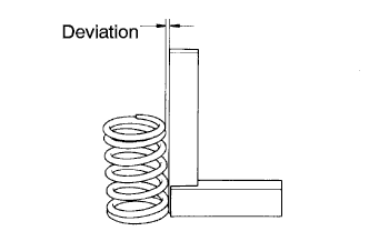
Using steel squares, measure the deviation of the valve spring.
- Maximum deviation:
- 1.6 mm (0.063 in.)
 |
| 8. INSPECT INTAKE VALVE |
Using a gasket scraper, scrape off any carbon on the valve head.
 |
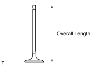
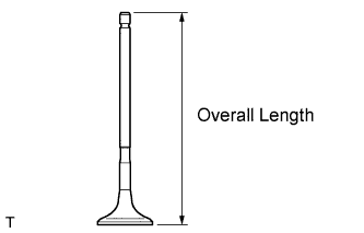
Using vernier calipers, measure the overall length of the valve.
- Standard overall length:
- 101.71 mm (4.0043 in.)
- Minimum overall length:
- 101.21 mm (3.9846 in.)
 |
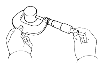
Using a micrometer, measure the diameter of the valve stem.
- Valve stem diameter:
- 5.470 to 5.485 mm (0.2154 to 0.2159 in.)
 |
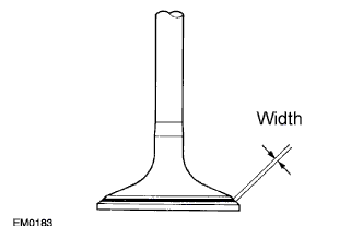
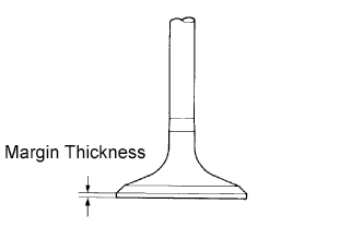
Using vernier calipers, measure the valve head margin thickness.
- Standard margin thickness:
- 1.05 to 1.45 mm (0.0413 to 0.0571 in.)
- Minimum margin thickness:
- 0.50 mm (0.0197 in.)
 |
| 9. INSPECT EXHAUST VALVE |
Using a gasket scraper, scrape off any carbon on the valve head.
|
Using vernier calipers, measure the overall length of the valve.
- Standard overall length:
- 101.15 mm (3.9823 in.)
- Minimum overall length:
- 100.70 mm (3.9646 in.)
 |
Using a micrometer, measure the diameter of the valve stem.
- Valve stem diameter:
- 5.465 to 5.480 mm (0.2152 to 0.2157 in.)
 |
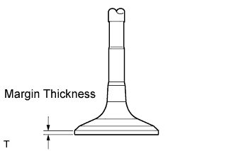
Using vernier calipers, measure the valve head margin thickness.
- Standard margin thickness:
- 1.20 to 1.60 mm (0.0472 to 0.0630 in.)
- Minimum margin thickness:
- 0.50 mm (0.0197 in.)
 |
| 10. INSPECT INTAKE VALVE GUIDE BUSH |
Using a caliper gauge, measure the inside diameter of the guide bush.
- Bushing inside diameter:
- 5.510 to 5.530 mm (0.2169 to 0.2177 in.)
 |
Subtract the valve stem diameter measurement from the guide bush inside diameter measurement.
- Standard oil clearance:
- 0.025 to 0.060 mm (0.0010 to 0.0024 in.)
- Maximum oil clearance:
- 0.080 mm (0.0031 in.)
| 11. INSPECT EXHAUST VALVE GUIDE BUSH |
Using a caliper gauge, measure the inside diameter of the guide bush.
- Bushing inside diameter:
- 5.510 to 5.530 mm (0.2169 to 0.2177 in.)
 |
Subtract the valve stem diameter measurement from the guide bushing inside diameter measurement.
- Standard oil clearance:
- 0.030 to 0.065 mm (0.0012 to 0.0026 in.)
- Maximum oil clearance:
- 0.100 mm (0.0039 in.)
| 12. INSPECT VALVE LIFTER |
Using a micrometer, measure the lifter diameter.
- Lifter diameter:
- 30.966 to 30.976 mm (1.2191 to 1.2195 in.)
 |
Using a caliper gauge, measure the lifter bore diameter of the cylinder head.
- Standard lifter bore diameter:
- 31.009 to 31.025 mm (1.2208 to 1.2215 in.)
 |
Subtract the lifter diameter measurement from the lifter bore diameter measurement.
- Standard oil clearance:
- 0.033 to 0.059 mm (0.0013 to 0.0023 in.)
- Maximum oil clearance:
- 0.070 mm (0.0028 in.)
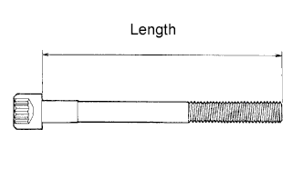
| 13. INSPECT CYLINDER HEAD SET BOLT |
Using vernier calipers, measure the length of the head bolts from the seat to the end.
- Standard bolt length:
- 141.3 to 142.7 mm (5.563 to 5.618 in.)
- Maximum bolt length:
- 144.2 mm (5.677 in.)
 |