Entry And Start System Front Passenger Side Door Entry Lock Function Does Not Operate
DESCRIPTION
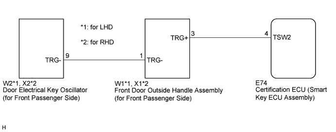
WIRING DIAGRAM
INSPECTION PROCEDURE
CHECK POWER DOOR LOCK OPERATION
READ VALUE USING INTELLIGENT TESTER (DOOR LOCK POSITION SWITCH)
READ VALUE USING INTELLIGENT TESTER (DOOR OUTSIDE HANDLE)
CHECK HARNESS AND CONNECTOR (FRONT DOOR OUTSIDE HANDLE - DOOR ELECTRICAL KEY OSCILLATOR)
CHECK HARNESS AND CONNECTOR (CERTIFICATION ECU - FRONT DOOR OUTSIDE HANDLE)
INSPECT FRONT DOOR OUTSIDE HANDLE ASSEMBLY (for Front Passenger Side)
REPLACE DOOR ELECTRICAL KEY OSCILLATOR (for Front Passenger Side)
CHECK DOOR ELECTRICAL KEY OSCILLATOR (for Front Passenger Side)
ENTRY AND START SYSTEM - Front Passenger Side Door Entry Lock Function does not Operate |
DESCRIPTION
If the front passenger side door entry lock function does not operate but the entry unlock function operates, the communication line between the vehicle and electrical key transmitter is normal. Any of the following components may have a malfunction: 1) touch sensor circuit certification ECU (smart key ECU assembly); 2) front door outside handle assembly (for front passenger side); or 3) door electrical key oscillator (for front passenger side).
WIRING DIAGRAM
INSPECTION PROCEDURE
- NOTICE:
- The entry and start system (for entry function) uses a multiplex communication system (LIN communication system) and CAN communication system. Inspect the communication function by following How to Proceed with Troubleshooting (CAMRY_ACV40 RM000000XU703SX.html). Troubleshoot the entry and start system (for entry function) after confirming that the communication system is functioning properly.
- Check that there are no electrical key transmitters in the vehicle.
| 1.CHECK POWER DOOR LOCK OPERATION |
When the door control switch on the master switch assembly is operated, check that the locked doors unlock (CAMRY_ACV40 RM00000133302LX.html).
- OK:
- Locked doors unlock.
| 2.READ VALUE USING INTELLIGENT TESTER (DOOR LOCK POSITION SWITCH) |
Connect the intelligent tester to the DLC3.
Turn the engine switch on (IG).
Turn the intelligent tester on.
Enter the following menus: Body / Main Body / Data List.
Read the Data List according to the display on the intelligent tester.
Main Body (Main Body ECU (Instrument Panel Junction Block))Tester Display
| Measurement Item/Range
| Normal Condition
| Diagnostic Note
|
P-Door Lock Pos SW
| Front passenger side door lock position switch signal/ON or OFF
| ON: Front passenger side door is unlocked
OFF: Front passenger side door is locked
| -
|
- OK:
- On the intelligent tester screen, the display changes between ON and OFF as shown in the chart above.
| 3.READ VALUE USING INTELLIGENT TESTER (DOOR OUTSIDE HANDLE) |
Enter the following menus: Body / Entry & Start / Data List.
Read the Data List according to the display on the intelligent tester.
Entry & Start (Certification ECU (Smart Key ECU Assembly))Tester Display
| Measurement Item/Range
| Normal Condition
| Diagnostic Note
|
P-Door Trigger SW
| Front passenger side door lock switch / ON or OFF
| ON: Entry lock switch is pressed
OFF: Entry lock switch is not pressed
| -
|
- OK:
- On the intelligent tester screen, the display changes between ON and OFF according to the chart above.
| OK |
|
|
|
| REPLACE CERTIFICATION ECU (SMART KEY ECU ASSEMBLY) |
|
| 4.CHECK HARNESS AND CONNECTOR (FRONT DOOR OUTSIDE HANDLE - DOOR ELECTRICAL KEY OSCILLATOR) |
Disconnect the front door outside handle assembly (for front passenger side) connector.
Disconnect the door electrical key oscillator (for front passenger side) connector.
Measure the resistance according to the value(s) in the table below.
- Standard Resistance:
for LHDTester Connection
| Condition
| Specified Condition
|
W1-1 (TRG-) - W2-9 (TRG-)
| Always
| Below 1 Ω
|
W1-1 (TRG-) - Body ground
| Always
| 10 kΩ or higher
|
for RHDTester Connection
| Condition
| Specified Condition
|
X1-1 (TRG-) - X2-9 (TRG-)
| Always
| Below 1 Ω
|
X1-1 (TRG-) - Body ground
| Always
| 10 kΩ or higher
|
| | REPAIR OR REPLACE HARNESS OR CONNECTOR |
|
|
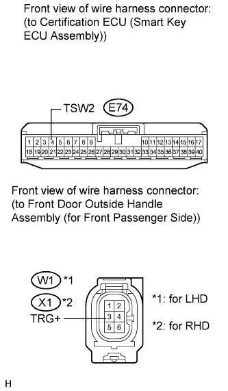
| 5.CHECK HARNESS AND CONNECTOR (CERTIFICATION ECU - FRONT DOOR OUTSIDE HANDLE) |
Disconnect the certification ECU (smart key ECU assembly) connector.
Measure the resistance according to the value(s) in the table below.
- Standard Resistance:
for LHDTester Connection
| Condition
| Specified Condition
|
E74-4 (TSW2) - W1-3 (TRG+)
| Always
| Below 1 Ω
|
E74-4 (TSW2) - Body ground
| Always
| 10 kΩ or higher
|
for RHDTester Connection
| Condition
| Specified Condition
|
E74-4 (TSW2) - X1-3 (TRG+)
| Always
| Below 1 Ω
|
E74-4 (TSW2) - Body ground
| Always
| 10 kΩ or higher
|
| | REPAIR OR REPLACE HARNESS OR CONNECTOR |
|
|
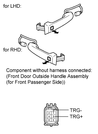
| 6.INSPECT FRONT DOOR OUTSIDE HANDLE ASSEMBLY (for Front Passenger Side) |
Measure the resistance according to the value(s) in the table below.
- Standard Resistance:
Tester Connection
| Switch Condition
| Specified Condition
|
1 (TRG-) - 3 (TRG+)
| Lock switch not pushed
| 10 kΩ or higher
|
1 (TRG-) - 3 (TRG+)
| Lock switch pushed
| Below 1 Ω
|
| 7.REPLACE DOOR ELECTRICAL KEY OSCILLATOR (for Front Passenger Side) |
Replace the door electrical key oscillator (for front passenger side) (CAMRY_ACV40 RM000001LTN00AX.html).
| 8.CHECK DOOR ELECTRICAL KEY OSCILLATOR (for Front Passenger Side) |
Check that the entry functions operate normally (CAMRY_ACV40 RM000002U9W010X.html).
- OK:
- Entry functions operate normally.
| | REPLACE CERTIFICATION ECU (SMART KEY ECU ASSEMBLY) |
|
|
| OK |
|
|
|
| END (DOOR ELECTRICAL KEY OSCILLATOR WAS DEFECTIVE) |
|