Entry And Start System Front Passenger Side Door Entry Lock And Unlock Functions Do Not Operate
DESCRIPTION
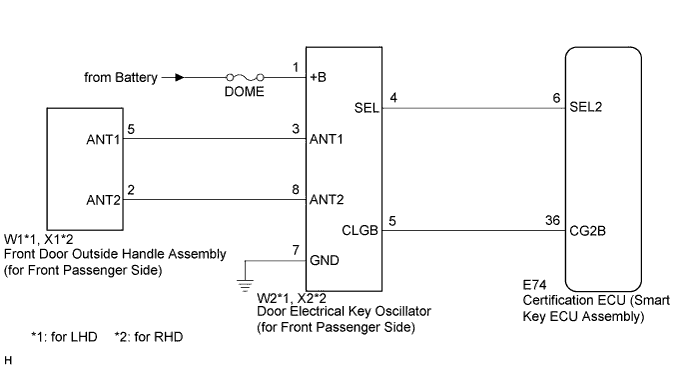
WIRING DIAGRAM
INSPECTION PROCEDURE
CHECK POWER DOOR LOCK OPERATION
READ VALUE USING INTELLIGENT TESTER (DOOR OUTSIDE HANDLE)
CHECK WAVE ENVIRONMENT
PERFORM KEY DIAGNOSTIC MODE INSPECTION
CHECK HARNESS AND CONNECTOR (CERTIFICATION ECU - DOOR ELECTRICAL KEY OSCILLATOR)
CHECK HARNESS AND CONNECTOR (DOOR ELECTRICAL KEY OSCILLATOR - FRONT DOOR OUTSIDE HANDLE)
INSPECT FUSE (DOME)
CHECK HARNESS AND CONNECTOR (DOOR ELECTRICAL KEY OSCILLATOR - BATTERY AND BODY GROUND)
REPLACE DOOR ELECTRICAL KEY OSCILLATOR (for Front Passenger Side)
CHECK DOOR ELECTRICAL KEY OSCILLATOR (for Front Passenger Side)
ENTRY AND START SYSTEM - Front Passenger Side Door Entry Lock and Unlock Functions do not Operate |
DESCRIPTION
When the front passenger door entry lock and unlock functions do not operate, any of the following may be malfunctioning: 1) power door lock control system; 2) door electrical key oscillator (for front passenger side); or 3) certification ECU (smart key ECU assembly).
WIRING DIAGRAM
INSPECTION PROCEDURE
- NOTICE:
- The entry and start system (for entry function) uses a multiplex communication system (LIN communication system) and CAN communication system. Inspect the communication function by following How to Proceed with Troubleshooting (CAMRY_ACV40 RM000000XU703SX.html). Troubleshoot the entry and start system (for entry function) after confirming that the communication system is functioning properly.
- Check that there are no electrical key transmitters in the vehicle.
| 1.CHECK POWER DOOR LOCK OPERATION |
When the door control switch on the master switch assembly is operated, check that the locked doors unlock (CAMRY_ACV40 RM00000133302LX.html).
- OK:
- Locked doors unlock.
| 2.READ VALUE USING INTELLIGENT TESTER (DOOR OUTSIDE HANDLE) |
Connect the intelligent tester to the DLC3.
Turn the engine switch on (IG).
Turn the intelligent tester on.
Enter the following menus: Body / Entry & Start / Data List.
Read the Data List according to the display on the intelligent tester.
Entry & Start (Certification ECU (Smart Key ECU Assembly))Tester Display
| Measurement Item/Range
| Normal Condition
| Diagnostic Note
|
P Touch Sensor
| Front passenger side door touch sensor / ON or OFF
| ON: Touch sensor is touched
OFF: Touch sensor is not touched
| -
|
P Trigger SW
| Front passenger side door lock switch / ON or OFF
| ON: Entry lock switch is pressed
OFF: Entry lock switch is not pressed
| -
|
- OK:
- On the intelligent tester screen, the display changes between ON and OFF according to the chart above.
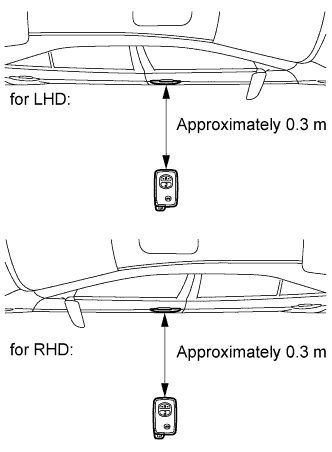
Bring the electrical key transmitter near the front door outside handle assembly (for front passenger side), and perform a front passenger door entry lock and unlock operation check.
- NOTICE:
- If the key is brought within 0.2 m (0.656 ft.) of the door outside handle assembly, communication is not possible.
- HINT:
- When pressing the lock switch, hold the electrical key transmitter about 1 m (3.28 ft.) above the ground and about 0.3 m (0.984 ft.) away from the vehicle as shown in the illustration.
- When the electrical key transmitter is brought near the front door outside handle assembly (for front passenger side), the possibility of wave interference decreases, and it can be determined if wave interference is causing the problem symptom.
- If the inspection result is that the operation check is normal, the possibility of wave interference is high. Also, added vehicle components may cause wave interference. If installed, remove them and perform the operation check.
- OK:
- Entry functions operate normally.
| OK |
|
|
|
| AFFECTED BY WAVE INTERFERENCE |
|
| 4.PERFORM KEY DIAGNOSTIC MODE INSPECTION |
Diagnostic mode inspection (door electrical key oscillator (for front passenger side))
Connect the intelligent tester to the DLC3.
Turn the engine switch on (IG).
Turn the intelligent tester on.
Enter the following menus: Body / Entry & Start / Utility / Key Communication Check / Overhead + Passenger Side.
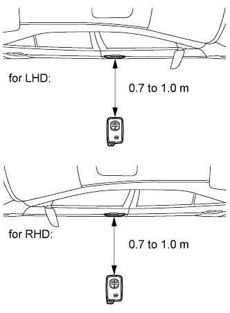
When the electrical key transmitter is in the position shown in the illustration, check that the wireless door lock buzzer sounds.
- HINT:
- If the buzzer sounds, it can be determined that the door electrical key oscillator (for front passenger side) is operating normally.
- Hold the electrical key transmitter at the same height as the door outside handle (0.7 to 1.0 m (2.30 to 3.28 ft.)). Make sure that the direction of the key is as shown in the illustration.
- OK:
- Wireless door lock buzzer sounds.
| OK |
|
|
|
| REPLACE CERTIFICATION ECU (SMART KEY ECU ASSEMBLY) |
|
| 5.CHECK HARNESS AND CONNECTOR (CERTIFICATION ECU - DOOR ELECTRICAL KEY OSCILLATOR) |
Disconnect the certification ECU (smart key ECU assembly) connector.
Disconnect the door electrical key oscillator (for front passenger side) connector.
Measure the resistance according to the value(s) in the table below.
- Standard Resistance:
for LHDTester Connection
| Condition
| Specified Condition
|
E74-6 (SEL2) - W2-4 (SEL)
| Always
| Below 1 Ω
|
E74-36 (CG2B) - W2-5 (CLGB)
| Always
| Below 1 Ω
|
E74-6 (SEL2) - Body ground
| Always
| 10 kΩ or higher
|
E74-36 (CG2B) - Body ground
| Always
| 10 kΩ or higher
|
for RHDTester Connection
| Condition
| Specified Condition
|
E74-6 (SEL2) - X2-4 (SEL)
| Always
| Below 1 Ω
|
E74-36 (CG2B) - X2-5 (CLGB)
| Always
| Below 1 Ω
|
E74-6 (SEL2) - Body ground
| Always
| 10 kΩ or higher
|
E74-36 (CG2B) - Body ground
| Always
| 10 kΩ or higher
|
| | REPAIR OR REPLACE HARNESS OR CONNECTOR |
|
|
| 6.CHECK HARNESS AND CONNECTOR (DOOR ELECTRICAL KEY OSCILLATOR - FRONT DOOR OUTSIDE HANDLE) |
Disconnect the front door outside handle assembly (for front passenger side) connector.
Measure the resistance according to the value(s) in the table below.
- Standard Resistance:
for LHDTester Connection
| Condition
| Specified Condition
|
W1-2 (ANT2) - W2-8 (ANT2)
| Always
| Below 1 Ω
|
W1-5 (ANT1) - W2-3 (ANT1)
| Always
| Below 1 Ω
|
W1-2 (ANT2) - Body ground
| Always
| 10 kΩ or higher
|
W1-5 (ANT1) - Body ground
| Always
| 10 kΩ or higher
|
for RHDTester Connection
| Condition
| Specified Condition
|
X1-2 (ANT2) - X2-8 (ANT2)
| Always
| Below 1 Ω
|
X1-5 (ANT1) - X2-3 (ANT1)
| Always
| Below 1 Ω
|
X1-2 (ANT2) - Body ground
| Always
| 10 kΩ or higher
|
X1-5 (ANT1) - Body ground
| Always
| 10 kΩ or higher
|
| | REPAIR OR REPLACE HARNESS OR CONNECTOR |
|
|
Remove the DOME fuse from the instrument panel junction block assembly.
Measure the resistance according to the value(s) in the table below.
- Standard Resistance:
Tester Connection
| Condition
| Specified Condition
|
DOME fuse
| Always
| Below 1 Ω
|
| 8.CHECK HARNESS AND CONNECTOR (DOOR ELECTRICAL KEY OSCILLATOR - BATTERY AND BODY GROUND) |
Measure the voltage according to the value(s) in the table below.
- Standard Voltage:
for LHDTester Connection
| Condition
| Specified Condition
|
W2-1 (+B) - W2-7 (GND)
| Always
| 11 to 14 V
|
for RHDTester Connection
| Condition
| Specified Condition
|
X2-1 (+B) - X2-7 (GND)
| Always
| 11 to 14 V
|
| | REPAIR OR REPLACE HARNESS OR CONNECTOR |
|
|
| 9.REPLACE DOOR ELECTRICAL KEY OSCILLATOR (for Front Passenger Side) |
Replace the door electrical key oscillator (for front passenger side) (CAMRY_ACV40 RM000001LTN00AX.html).
| 10.CHECK DOOR ELECTRICAL KEY OSCILLATOR (for Front Passenger Side) |
Check that the entry functions operate normally (CAMRY_ACV40 RM000002U9W010X.html).
- OK:
- Entry functions operate normally.
| | REPLACE CERTIFICATION ECU (SMART KEY ECU ASSEMBLY) |
|
|
| OK |
|
|
|
| END (DOOR ELECTRICAL KEY OSCILLATOR WAS DEFECTIVE) |
|