Vehicle Stability Control System -- System Description |
| FUNCTION DESCRIPTION |
- HINT:
- The skid control ECU is located within the brake actuator assembly.
- The yaw rate sensor and acceleration sensor are combined in a single unit. This unit communicates with the skid control ECU through CAN communication.
ABS (Anti-lock Brake System)
The ABS helps prevent the wheels from locking when the brakes are applied firmly or when braking on a slippery surface.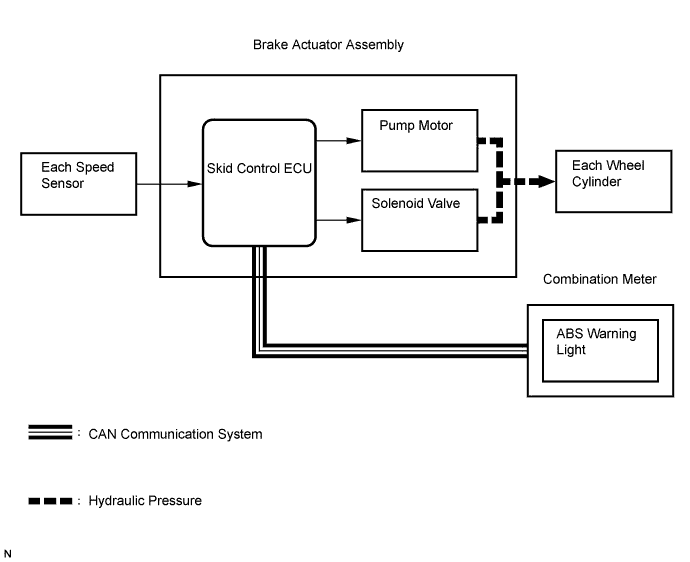
Operation description
The skid control ECU detects wheel lock based on speed signals it receives from the wheel speed sensors. Based on this information, the skid control ECU controls the pump motor and solenoid valves. The pump motor and solenoid valves are used to prevent wheel lock by controlling the hydraulic pressure applied to the brakes at each wheel. The ABS warning light will come on when the system is malfunctioning.
EBD (Electronic Brake force Distribution)
The EBD control utilizes ABS, and performs proper brake force distribution between the front and rear wheels in accordance with driving conditions.
When braking while cornering, it also controls the brake forces of the right and left wheels, helping to maintain vehicle behavior.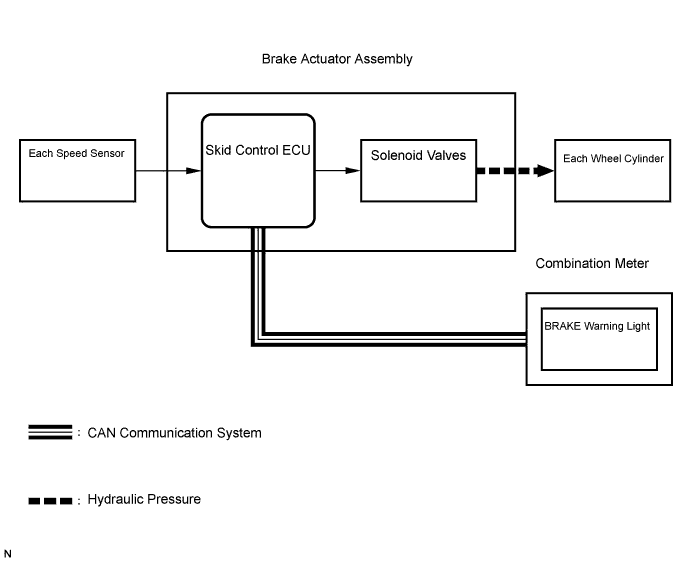
Operation description
The skid control ECU receives a speed signal from each wheel speed sensor, and uses these signals to detect locking of the wheels. The ECU uses this information in order to determine appropriate control of the solenoid valves.
The solenoid valves control the hydraulic pressure applied to the brake cylinder at each wheel. In this way, the solenoid valves are used to control the brake power split between the front and rear, and left and right wheels. The BRAKE warning light will come on if there is a malfunction in the EBD system.
BA (Brake Assist)
The primary purpose of the brake assist system is to provide auxiliary brake force to assist the driver who cannot generate a large enough brake force during emergency braking, thus helping to maximize the brake performance of the vehicle.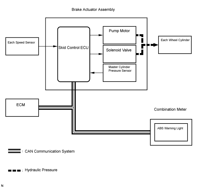
Operation description
The skid control ECU receives the speed signal from each speed sensor and the fluid pressure signal from the master cylinder pressure sensor to determine whether brake assist is necessary. If brake assist is necessary, the skid control ECU sends control signals to the pump motor and solenoid. The pump and the solenoid valve then control the pressure applied to each wheel cylinder.
The ABS warning light comes on to indicate a malfunction in the BA system.
TRC (Traction Control)
The TRC system helps prevent the drive wheels from slipping when the driver depresses the accelerator pedal excessively when starting off or accelerating on a slippery surface.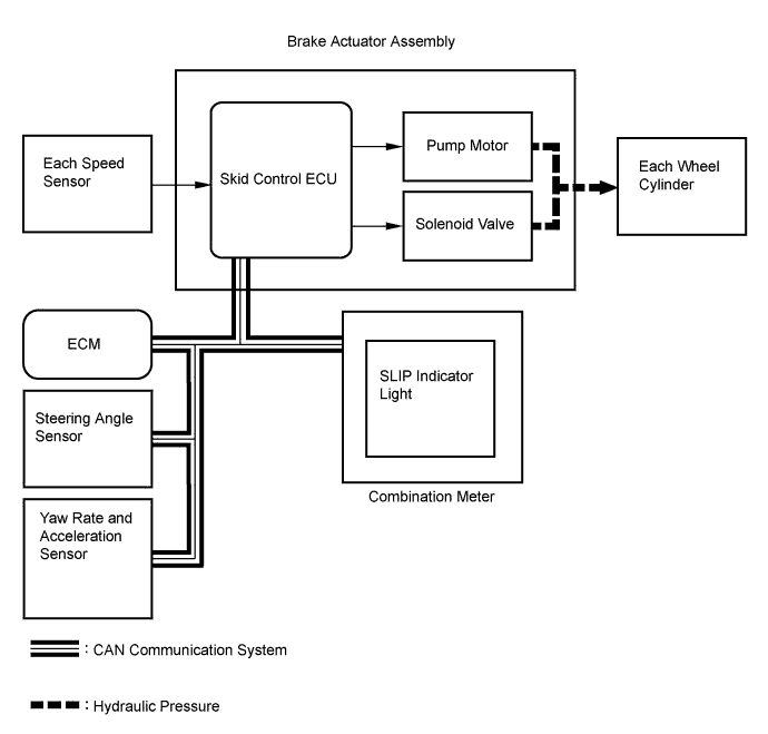
Operation description
The skid control ECU detects wheelspin by receiving signals from each speed sensor and the ECM via CAN communication. The skid control ECU controls engine torque with the ECM via CAN communication and brake hydraulic pressure through the pump and solenoid valve.
The SLIP indicator light blinks when the system is operating. When there is a malfunction in the TRC system, the SLIP indicator light will come on.
VSC (Vehicle Stability Control)
The VSC system helps prevent the vehicle from slipping sideways as a result of strong front or rear wheel skid during cornering.
Operation description
The skid control ECU determines the vehicle operating conditions based on signals received from the wheel speed sensors, yaw rate and acceleration sensor, and steering angle sensor. The skid control ECU sends signals via CAN communication to the ECM in order to control engine torque. The skid control ECU controls brake hydraulic pressure using the pump and solenoid valves.
The SLIP indicator light will blink, and the skid control buzzer will sound when the system is operating. If a malfunction occurs in the VSC system, the SLIP indicator light will come on.
| ABS with EBD, BA, TRC and VSC OPERATION |
The skid control ECU calculates vehicle stability tendency based on the signals from the speed sensor, yaw rate and acceleration sensor, and steering angle sensor. In addition, it evaluates the results of the calculations to determine whether any control actions (control of the engine output torque by electronic throttle control and of the wheel brake pressure by the brake actuator assembly) should be implemented.
The SLIP indicator light blinks and the skid control buzzer sounds to inform the driver that the VSC system is operating. The SLIP indicator light also blinks when traction control is operating, and the operation being performed is displayed.
| FAIL SAFE |
When a failure occurs in the ABS with BA, TRC and VSC systems, the ABS warning and SLIP indicator lights come on and ABS with BA, TRC and VSC operations are prohibited. In addition, when there is a failure that disables the EBD operation, the BRAKE warning light also comes on and the EBD operation is prohibited.
If control is prohibited due to a malfunction during operation, control will be disabled gradually.
This is to avoid sudden vehicle instability.
| INITIAL CHECK |
When the vehicle speed first becomes approximately 4 mph (6 km/h) or more after the ignition switch is turned on (IG), each solenoid valve and motor of the brake actuator is sequentially activated to perform an electrical check. During the initial check, the operating sound of solenoid valve and motor can be heard from the engine compartment, but this is not a malfunction.
| INSPECTION MODE |
VSC operation can be disabled by operating the intelligent tester.
- HINT:
- Refer to the intelligent tester operator's manual for further details.
| FUNCTION OF COMPONENTS |
| Components | Function |
| Speed sensor | Detects the wheel speed and sends the signal to the skid control ECU. |
| Skid control ECU (housed in brake actuator assembly) |
|
| Brake actuator assembly |
|
| Solenoid relay |
|
| Motor relay (VSC NO. 2 relay) | Supplies power to the pump motor. |
| Fail safe relay (VSC NO. 1 relay) | Cuts off power to the motor when the pump motor circuit malfunctions. |
| Steering angle sensor |
|
| Yaw rate and acceleration sensor |
|
| Master cylinder pressure sensor |
|
| Stop light switch | Detects the brake operating conditions and inputs the results to the skid control ECU. |
| ECM | Controls the engine output when TRC and VSC are operating with the skid control ECU via CAN communication. |
| Skid control buzzer | Intermittently sounds to inform the driver that the VSC is operating. |
| ABS warning light |
|
| BRAKE warning light |
|
| SLIP indicator light |
|
| Multi information display | Displays to output DTCs. |