Airbag System -- Diagnosis System |
| CHECK DLC3 |
The ECU uses ISO 15765-4 for communication.
The terminal arrangement of the DLC3 complies with ISO 150312-3 and matches the ISO 15765-4 format.Symbols (Terminal No.) Terminal Description Condition Specified Condition SIL (7) - SG (5) Bus "+" line During transmission Pulse generation CG (4) - Body ground Chassis ground Always Below 1 Ω SG (5) - Body ground Signal ground Always Below 1 Ω BAT (16) - Body ground Battery positive Always 11 to 14 V CANH (6) - CANL (14) CAN bus line Ignition switch off (*) 54 to 69 Ω CANH (6) - BAT (16) HIGH-level CAN bus line Ignition switch off (*) 6 kΩ or higher CANH (6) - CG (4) HIGH-level CAN bus line Ignition switch off (*) 200 Ω or higher CANL (14) - BAT (16) LOW-level CAN bus line Ignition switch off (*) 6 kΩ or higher CANL (14) - CG (4) LOW-level CAN bus line Ignition switch off (*) 200 Ω or higher - NOTICE:
- *: Before measuring the resistance, leave the vehicle as is for at least 1 minute and do not operate the ignition switch, any other switches, or the doors.
- HINT:
- If the display shows a communication error message when connecting the cable of the intelligent tester to the DLC3, turning the ignition switch to the ON position and operating the intelligent tester, there is a problem on the vehicle side or tester side.
- If communication is normal when the tester is connected to another vehicle, inspect the DLC3 on the original vehicle.
- If communication is still not possible when the tester is connected to another vehicle, the problem is probably in the tester itself. Consult the Service Department listed in the tester's instruction manual.
 |
| SYMPTOM SIMULATION |
- HINT:
- The most difficult case in troubleshooting is when no symptoms occur. In such cases, a thorough customer problem analysis must be carried out. Then the same or similar conditions and environment in which the problem occurred in the customer's vehicle should be reproduced. No matter how experienced or skilled a technician may be, if he proceeds to troubleshoot without confirming the problem symptoms, he will likely overlook something important and make a wrong guess at some points in the repair operation.
- This leads to a standstill in troubleshooting.
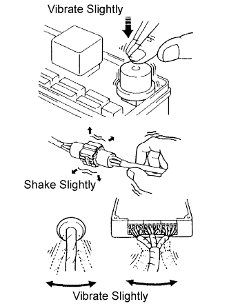
Vibration method: When vibration seems to be the major cause.
- HINT:
- Perform the simulation method only during the primary check period (for approximately 6 seconds after the ignition switch is turned to the ON position).
Slightly vibrate the part of the sensor considered to be the problem cause with your fingers and check whether the malfunction occurs.
- HINT:
- Shaking the relays too strongly may result in open relays.
Slightly shake the connector vertically and horizontally.
Slightly shake the wire harness vertically and horizontally.
The connector joint and fulcrum of the vibration are the major areas to be checked thoroughly.
 |
| FUNCTION OF SRS WARNING LIGHT |
Primary check.
Turn the ignition switch to the LOCK position. Wait for at least 2 seconds, then turn the ignition switch to the ON position. The SRS warning light comes on for approximately 6 seconds and the diagnosis of the airbag system (including the seat belt pretensioners) is performed.
- HINT:
- If trouble is detected during the primary check, the SRS warning light remains on even after the primary check period (for approximately 6 seconds) has elapsed.
Constant check.
After the primary check, the center airbag sensor assembly constantly monitors the airbag system for trouble.
- HINT:
- If trouble is detected during the constant check, the center airbag sensor assembly functions as follows:
- The SRS warning light comes on.
- The SRS warning light goes off, and then comes on. This blinking pattern indicates a source voltage drop. The SRS warning light goes off 10 seconds after the source voltage returns to normal.
Review.
When the airbag system is normal:
The SRS warning light comes on only during the primary check period (for approximately 6 seconds after the ignition switch is turned to the ON position).When the airbag system has trouble:
- The SRS warning light remains on even after the primary check period has elapsed.
- The SRS warning light goes off after the primary check, but comes on again during the constant check.
- The SRS warning light does not come on when turning the ignition switch from LOCK to ON.
- HINT:
- The center airbag sensor assembly keeps the SRS warning light on if the airbag has been deployed.
- The SRS warning light remains on even after the primary check period has elapsed.
| SRS WARNING LIGHT CHECK |
Turn the ignition switch to the ON position, and check that the SRS warning light comes on for approximately 6 seconds (primary check).
Check that the SRS warning light goes off approximately 6 seconds after the ignition switch is turned to the ON position (constant check).
- HINT:
- When any of the following symptoms occur, refer to "Problem Symptoms Table" (CAMRY_ACV40 RM000000XFA04HX.html).
- The SRS warning light comes on occasionally, after the primary check period has elapsed.
- The SRS warning light comes on, but a DTC is not output.
- The ignition switch is turned from LOCK to ON, but the SRS warning light does not come on.
 |
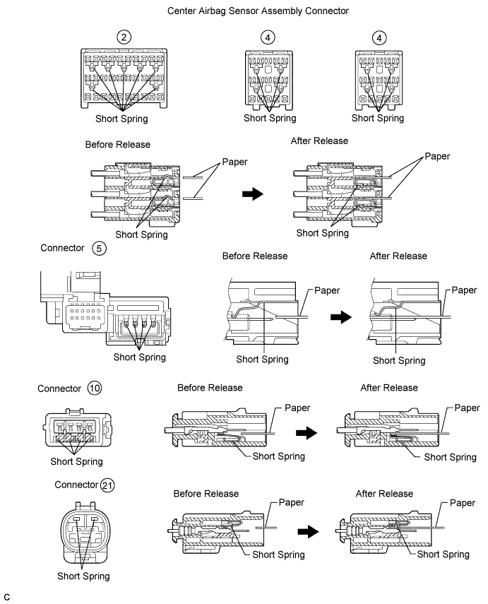
| ACTIVATION PREVENTION MECHANISM |
FUNCTION OF ACTIVATION PREVENTION MECHANISM
An activation prevention mechanism is built into the connector (on the center airbag sensor assembly side) of the airbag system squib circuit to prevent accidental airbag activation.
This mechanism closes the circuit when the connector is disconnected by bringing the short spring into contact with the terminals and shutting off external electricity to prevent accidental airbag activation.
RELEASE METHOD OF ACTIVATION PREVENTION MECHANISM
To release the activation prevention mechanism, insert a piece of paper with the same thickness as the male terminal (approximately 0.5 mm (0.020 in.)) between the terminals and the short spring to break the connection.
Refer to the following illustrations concerning connectors utilizing the activation prevention mechanism and its release method.
- CAUTION:
- Never release the activation prevention mechanism on the squib connector even when inspecting with the squib disconnected.
- NOTICE:
- Do not release the activation prevention mechanism unless specially directed by the troubleshooting procedure.
- To prevent the terminal and the short spring from being damaged, always use a piece of paper with the same thickness as the male terminal.