DESCRIPTION
WIRING DIAGRAM
INSPECTION PROCEDURE
CHECK THAT MIL IS ILLUMINATED
CHECK WHETHER MIL TURNS OFF
CHECK HARNESS AND CONNECTOR (CHECK FOR SHORT IN WIRE HARNESS)
CHECK HARNESS AND CONNECTOR (COMBINATION METER - ECM)
CHECK THAT MIL IS ILLUMINATED
CHECK THAT ENGINE STARTS
INSPECT COMBINATION METER ASSEMBLY (MIL CIRCUIT)
DESCRIPTION
The MIL (Malfunction Indicator Lamp) is used to indicate vehicle malfunction detected by the ECM. When the ignition switch is turned to the ON position, power is supplied to the MIL circuit, and the ECM provides the circuit ground which illuminates the MIL.The MIL operation can be checked visually: When the ignition switch is first turned to the ON position, the MIL should be illuminated and should then turn off. If the MIL remains illuminated or is not illuminated, conduct the following troubleshooting procedure using the intelligent tester.
WIRING DIAGRAM
INSPECTION PROCEDURE
| 1.CHECK THAT MIL IS ILLUMINATED |
Perform troubleshooting in accordance with the table below.
- Result:
Condition
| Proceed to
|
MIL remains ON
| A
|
MIL does not illuminate
| B
|
| 2.CHECK WHETHER MIL TURNS OFF |
Connect the intelligent tester to the DLC3.
Turn the ignition switch to the ON position and turn the tester on.
Select the following menu items: Powertrain / Engine and ECT / DTC.
Check if any DTCs have been stored. Note down any DTCs.
Clear the DTCs (CAMRY_ACV40 RM000000PDK081X.html).
Check if the MIL goes off.
- Standard:
- MIL goes off.
| | REPAIR CIRCUITS INDICATED BY OUTPUT DTCS |
|
|
| 3.CHECK HARNESS AND CONNECTOR (CHECK FOR SHORT IN WIRE HARNESS) |
Disconnect the A24 ECM connector.
Turn the ignition switch to the ON position.
Check that the MIL is not illuminated.
- OK:
- MIL is not illuminated.
Reconnect the ECM connector.
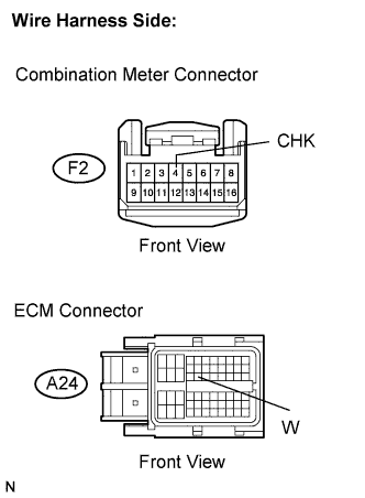
| 4.CHECK HARNESS AND CONNECTOR (COMBINATION METER - ECM) |
Disconnect the F2 combination meter connector.
Disconnect the A24 ECM connector.
Measure the resistance between the terminals of the wire harness side connectors.
- Standard resistance (Check for short):
Tester Connection
| Specified Condition
|
W (A24-24) or CHK (F2-4) - Body ground
| 10 kΩ or higher
|
Reconnect the combination meter connector.
Reconnect the ECM connector.
| | REPAIR OR REPLACE COMBINATION METER ASSEMBLY |
|
|
| NG |
|
|
|
| REPAIR OR REPLACE HARNESS OR CONNECTOR |
|
| 5.CHECK THAT MIL IS ILLUMINATED |
Check if the MIL is illuminated when the ignition switch is turned to the ON position.
- OK:
- MIL is illuminated.
| 6.CHECK THAT ENGINE STARTS |
Turn the ignition switch to the ON position.
Start the engine.
- Result:
Result
| Proceed to
|
Engine starts
| A
|
Engine does not start*
| B
|
- HINT:
- *: The intelligent tester cannot communicate with the ECM.
| 7.INSPECT COMBINATION METER ASSEMBLY (MIL CIRCUIT) |
Check the MIL circuit (CAMRY_ACV40 RM0000012GB029X.html).
| | REPAIR OR REPLACE COMBINATION METER ASSEMBLY |
|
|
| OK |
|
|
|
| CHECK AND REPLACE HARNESS AND CONNECTOR (COMBINATION METER - ECM) |
|