Automatic Transaxle System Transmission Control Switch Circuit
DESCRIPTION
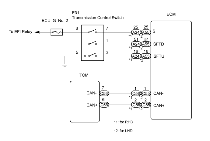
WIRING DIAGRAM
INSPECTION PROCEDURE
CHECK HARNESS AND CONNECTOR (BATTERY - TRANSMISSION CONTROL SWITCH)
CHECK HARNESS AND CONNECTOR (TRANSMISSION CONTROL SWITCH - BODY GROUND)
INSPECT TRANSMISSION CONTROL SWITCH
CHECK HARNESS AND CONNECTOR (TRANSMISSION CONTROL SWITCH - ECM)
AUTOMATIC TRANSAXLE SYSTEM - Transmission Control Switch Circuit |
DESCRIPTION
When moving the shift lever into the S position using the transmission control switch, it is possible to switch the shift range position between "1" (first range) and "6" (sixth range).Shifting up "+" once raises one shift range position, and shifting down "-" lowers one shift range position.
WIRING DIAGRAM
INSPECTION PROCEDURE
| 1.CHECK HARNESS AND CONNECTOR (BATTERY - TRANSMISSION CONTROL SWITCH) |
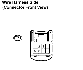
Disconnect the transmission control switch connector of the shift lock control unit assembly.
Measure the voltage according to the value(s) in the table below.
- Standard voltage:
Switch Condition
| Tester Connection
| Specified Condition
|
Ignition switch ON
| 3 - Body ground
| 10 to 14 V
|
Ignition switch OFF
| Below 1 V
|
| | REPAIR OR REPLACE HARNESS OR CONNECTOR |
|
|
| 2.CHECK HARNESS AND CONNECTOR (TRANSMISSION CONTROL SWITCH - BODY GROUND) |
Measure the resistance according to the value(s) in the table below.
- Standard resistance:
Tester Connection
| Specified Condition
|
5 - Body ground
| Below 1 Ω
|
| | REPAIR OR REPLACE HARNESS OR CONNECTOR |
|
|
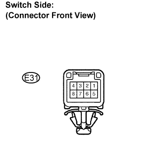
| 3.INSPECT TRANSMISSION CONTROL SWITCH |
Measure the resistance between each terminal of the shift lock control unit assembly when the shift lever is moved to each position.
- Standard resistance:
Shift Position
| Tester Connection
| Specified Condition
|
S, "+" and "-"
| 3 - 7
| Below 1 Ω
|
Except S, "+" and "-"
| 10 kΩ or higher
|
Press continuously
"+"
(Up shift)
| 2 - 5
| Below 1 Ω
|
S
| 10 kΩ or higher
|
Press continuously
"-"
(Down shift)
| 1 - 5
| Below 1 Ω
|
S
| 10 kΩ or higher
|
| | REPLACE TRANSMISSION CONTROL SWITCH |
|
|
| 4.CHECK HARNESS AND CONNECTOR (TRANSMISSION CONTROL SWITCH - ECM) |
Connect the transmission control switch connector of the shift lock control unit assembly.
Disconnect the A24*1 or A55*2 ECM connector.
Turn the ignition switch on, and measure the voltage according to the value(s) in the table below when the shift lever is moved to each position.
- Standard voltage:
Shift Position
| Tester Connection
| Specified Condition
|
S, "+" and "-"
| A24-25*1 (S) - Body ground
A55-25*2 (S) - Body ground
| 10 to 14 V
|
Except S, "+" and "-"
| Below 1 V
|
Turn the ignition switch off.
Disconnect the ECM connector.
*1: for RHD
*2: for LHD
Measure the resistance according to the value(s) in the table below when the shift lever is moved to each position.
- Standard resistance:
Shift Position
| Tester Connection
| Specified Condition
|
Press continuously
"+"
(Up shift)
| A24-16*1 (SFTU) - Body ground
A55-16*2 (SFTU) - Body ground
| Below 1 Ω
|
S
| 10 kΩ or higher
|
Press continuously
"-"
(Down shift)
| A24-51*1 (SFTD) - Body ground
A55-51*2 (SFTD) - Body ground
| Below 1 Ω
|
S
| 10 kΩ or higher
|
| | REPAIR OR REPLACE HARNESS OR CONNECTOR |
|
|
| OK |
|
|
|
| PROCEED TO NEXT CIRCUIT INSPECTION SHOWN IN PROBLEM SYMPTOMS TABLE |
|