Dtc P0031 Oxygen (A/F) Sensor Heater Control Circuit Low (Bank 1 Sensor 1)
DESCRIPTION
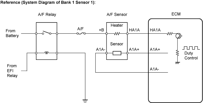
WIRING DIAGRAM
INSPECTION PROCEDURE
INSPECT AIR FUEL RATIO SENSOR (HEATER RESISTANCE)
CHECK TERMINAL VOLTAGE (+B OF A/F SENSOR)
INSPECT FUSE (A/F)
INSPECT ENGINE ROOM JUNCTION BLOCK (EFI RELAY, A/F RELAY)
INSPECT FUSE (EFI MAIN)
CHECK HARNESS AND CONNECTOR (A/F SENSOR - A/F RELAY)
CHECK HARNESS AND CONNECTOR
CHECK WHETHER DTC OUTPUT RECURS
DTC P0031 Oxygen (A/F) Sensor Heater Control Circuit Low (Bank 1 Sensor 1) |
DTC P0032 Oxygen (A/F) Sensor Heater Control Circuit High (Bank 1 Sensor 1) |
DTC P0051 Oxygen (A/F) Sensor Heater Control Circuit Low (Bank 2 Sensor 1) |
DTC P0052 Oxygen (A/F) Sensor Heater Control Circuit High (Bank 2 Sensor 1) |
DESCRIPTION
- HINT:
- Although the DTC titles include oxygen sensor, these DTCs relate to the Air-Fuel Ratio (A/F) sensor.
- Sensor 1 refers to the sensor mounted in front of the Three-Way Catalytic Converter (TWC) and located near the engine assembly.
The A/F sensor generates voltage* that corresponds to the actual air-fuel ratio. This sensor voltage is used to provide the ECM with feedback so that it can control the air-fuel ratio. The ECM determines the deviation from the stoichiometric air-fuel ratio level, and regulates the fuel injection time. If the A/F sensor malfunctions, the ECM is unable to control the air-fuel ratio accurately.The A/F sensor is the planar type and is integrated with the heater, which heats the solid electrolyte (zirconia element). This heater is controlled by the ECM. When the intake air volume is low (the exhaust gas temperature is low), a current flows into the heater to heat the sensor, in order to facilitate accurate oxygen concentration detection. In addition, the sensor and heater portions are narrower than the conventional type. The heat generated by the heater is conducted to the solid electrolyte through the alumina, therefore the sensor activation is accelerated.A three-way catalytic converter (TWC) is used in order to convert the carbon monoxide (CO), hydrocarbon (HC), and nitrogen oxide (NOx) into less harmful substances. To allow the TWC to function effectively, it is necessary to keep the air-fuel ratio of the engine near the stoichiometric air-fuel ratio.*: Value changes inside the ECM. Since the A/F sensor is the current output element, a current is converted to a voltage inside the ECM. Any measurements taken at the A/F sensor or ECM connectors will show a constant voltage.- HINT:
- When any of these DTCs are set, the ECM enters fail-safe mode. The ECM turns off the A/F sensor heater in fail-safe mode. Fail-safe mode continues until the ignition switch is turned off.
- The ECM provides a pulse width modulated control circuit to adjust the current through the heater. The A/F sensor heater circuit uses a relay on the B+ side of the circuit.
DTC No.
| DTC Detection Condition
| Trouble Area
|
P0031
P0051
| Air-Fuel Ratio (A/F) sensor heater (bank 1, 2, sensor 1) current is less than 0.8 A (1 trip detection logic)
| - Open in A/F sensor heater (bank 1, 2, sensor 1) circuit
- A/F sensor heater (bank 1, 2, sensor 1)
- A/F HTR relay
- ECM
|
P0032
P0052
| Air-Fuel Ratio (A/F) sensor heater (bank 1, 2, sensor 1) current is more than 10 A (1 trip detection logic)
| - Short in A/F sensor heater (bank 1, 2, sensor 1) circuit
- A/F sensor heater (sensor 1)
- A/F HTR relay
- ECM
|
- HINT:
- Bank 1 refers to the bank that includes cylinder No. 1.
- Bank 2 refers to the bank that does not include cylinder No. 1.
- Sensor 1 refers to the sensor closest to the engine assembly.
- Sensor 2 refers to the sensor farthest away from the engine assembly.
WIRING DIAGRAM
Refer to DTC P2195 (Link)
INSPECTION PROCEDURE
- HINT:
- Read freeze frame data using the intelligent tester. The ECM records vehicle and driving condition information as freeze frame data the moment a DTC is stored. When troubleshooting, freeze frame data can be helpful in determining whether the vehicle was running or stopped, whether the engine was warmed up or not, whether the air-fuel ratio was lean or rich, as well as other data recorded at the time of a malfunction (CAMRY_ACV40 RM000000PDS01FX.html).
| 1.INSPECT AIR FUEL RATIO SENSOR (HEATER RESISTANCE) |
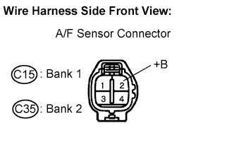
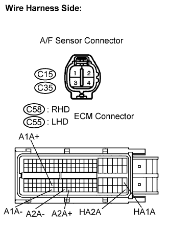
Disconnect the C15 or C35 A/F sensor connector.
Measure the resistance according to the value(s) in the table below.
- Standard resistance:
- Bank 1 sensor 1:
Tester Connection
| Condition
| Specified Condition
|
HA1A (1) - +B (2)
| 20°C (68°F)
| 1.8 to 3.4 Ω
|
HA1A (1) - A1A- (4)
| -
| 10 kΩ or higher
|
- Bank 2 sensor 1:
Tester Connection
| Condition
| Specified Condition
|
HA2A (1) - +B (2)
| 20°C (68°F)
| 1.8 to 3.4 Ω
|
HA2A (1) - A2A- (4)
| -
| 10 kΩ or higher
|
Reconnect the A/F sensor connector.
| 2.CHECK TERMINAL VOLTAGE (+B OF A/F SENSOR) |
Disconnect the C15 or C35 A/F sensor connector.
Turn the ignition switch to the ON position.
Measure the voltage between the terminals of the A/F sensor connector and body ground.
- Standard voltage:
Tester Connection
| Specified Condition
|
+B (C15-2) - Body ground
| 9 to 14 V
|
+B (C35-2) - Body ground
| 9 to 14 V
|
Remove the A/F sensor fuse from the No. 1 integration relay.
Measure the A/F sensor fuse resistance.
- Standard resistance:
- Below 1 Ω
Reinstall the A/F fuse.
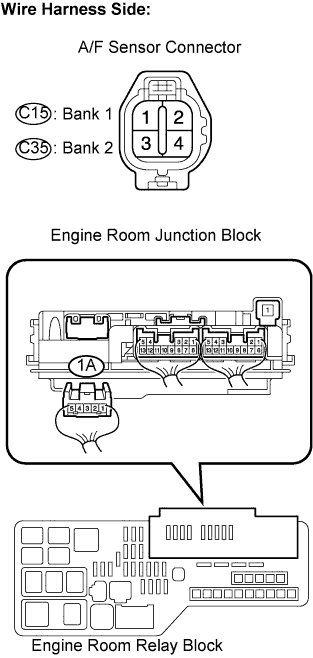
| 4.INSPECT ENGINE ROOM JUNCTION BLOCK (EFI RELAY, A/F RELAY) |
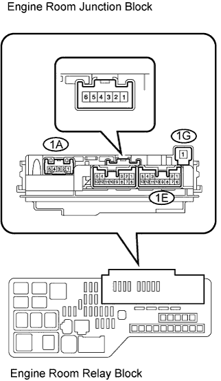
Remove the engine room junction block from the engine room R/B.
Inspect the EFI relay.
Measure the EFI relay resistance.
- Standard resistance:
Tester Connection
| Specified Condition
|
1E-12 - 1E-6
| 10 kΩ or higher
|
1E-12 - 1E-6
| Below 1 Ω
(Apply battery voltage between terminals 1E-9 and 1E-10)
|
Inspect the A/F relay.
Measure the A/F relay resistance.
- Standard resistance:
Tester Connection
| Specified Condition
|
1G-1 - 1A-4
| 10 kΩ or higher
|
1G-1 - 1A-4
| Below 1 Ω
(Apply battery voltage between terminals 1E-9 and 1E-10)
|
| | REPLACE NO. 1 INTEGRATION RELAY |
|
|
| 5.INSPECT FUSE (EFI MAIN) |
Remove the EFI MAIN fuse from the engine room R/B.
Measure the EFI MAIN fuse resistance.
- Standard resistance:
- Below 1 Ω
Reinstall the EFI MAIN fuse.
| 6.CHECK HARNESS AND CONNECTOR (A/F SENSOR - A/F RELAY) |
Disconnect the C15 or C35 A/F sensor connector.
Remove the engine room junction block from the engine room R/B.
Measure the resistance between the terminals.
- Standard resistance:
- Check for open:
Tester Connection
| Specified Condition
|
+B (C15-2) - 1A-4 (Engine room R/B)
| Below 1 Ω
|
+B (C35-2) - 1A-4 (Engine room R/B)
| Below 1 Ω
|
- Check for short:
Tester Connection
| Specified Condition
|
+B (C15-2) or 1A-4 (Engine room R/B) - Body ground
| 10 kΩ or higher
|
+B (C35-2) or 1A-4 (Engine room R/B) - Body ground
| 10 kΩ or higher
|
Reinstall the engine room junction block.
Reconnect the A/F sensor connector.
| | REPAIR OR REPLACE HARNESS OR CONNECTOR |
|
|
| OK |
|
|
|
| CHECK ECM POWER SOURCE CIRCUIT |
|
| 7.CHECK HARNESS AND CONNECTOR |
Disconnect the C15 or C35 A/F sensor connector.
Disconnect the C58 (RHD) or C55 (LHD) ECM connector.
Measure the resistance between the terminals.
- Standard resistance (Check for open):
- RHD:
Tester Connection
| Specified Condition
|
HA1A (C58-86) - HA1A (C15-1)
| Below 1 Ω
|
HA2A (C58-109) - HA2A (C35-1)
| Below 1 Ω
|
- LHD:
Tester Connection
| Specified Condition
|
HA1A (C55-86) - HA1A (C15-1)
| Below 1 Ω
|
HA2A (C55-109) - HA2A (C35-1)
| Below 1 Ω
|
- Standard resistance (Check for short):
- RHD:
Tester Connection
| Specified Condition
|
HA1A (C58-86) or HA1A (C15-1) - Body ground
| 10 kΩ or higher
|
HA2A (C58-109) or HA2A (C35-1) - Body ground
| 10 kΩ or higher
|
- LHD:
Tester Connection
| Specified Condition
|
HA1A (C55-86) or HA1A (C15-1) - Body ground
| 10 kΩ or higher
|
HA2A (C55-109) or HA2A (C35-1) - Body ground
| 10 kΩ or higher
|
Reconnect the ECM connector.
Reconnect the A/F sensor connectors.
| | REPAIR OR REPLACE HARNESS OR CONNECTOR |
|
|
| 8.CHECK WHETHER DTC OUTPUT RECURS |
Connect the intelligent tester to the DLC3.
Turn the ignition switch to the ON position.
Turn the intelligent tester ON.
Clear the DTCs (CAMRY_ACV40 RM000000PDK080X.html).
Start the engine.
Allow the engine to idle for 1 minute or more.
Select the following menu items: Powertrain / Engine / DTC.
Read the DTCs.
- Result:
Display (DTC Output)
| Proceed to
|
No output
| A
|
P0031, P0032, P0051 and/or P0052
| B
|
| A |
|
|
|
| CHECK FOR INTERMITTENT PROBLEMS |
|