Dtc P0500 Vehicle Speed Sensor A
DESCRIPTION
MONITOR DESCRIPTION
WIRING DIAGRAM
INSPECTION PROCEDURE
INSPECT SPEEDOMETER (METER OPERATION)
INSPECT TCM
DTC P0500 Vehicle Speed Sensor "A" |
DESCRIPTION
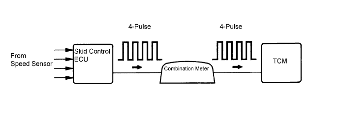
The speed sensors detect the wheel speed and sends the appropriate signals to the skid control ECU. The skid control ECU converts these wheel speed signals into a 4-pulse signal and outputs it to the TCM via the combination meter. The TCM determines the vehicle speed based on the frequency of these pulse signals.DTC No.
| DTC Detection Condition
| Trouble Area
|
P0500
| When the ECT sensor is normal and the counter gear speed is 300 rpm or more, the vehicle speed signal is not input for 2 seconds or more.
| - Vehicle speed sensor
- Vehicle speed sensor signal circuit
- Combination meter
- TCM
|
MONITOR DESCRIPTION
The TCM assumes that the vehicle is being driven when the transmission counter gear indicates more than 300 rpm and over 30 seconds have passed since the park/neutral position switch was turned off. If there is no signal from the vehicle speed sensor with these conditions satisfied, the TCM concludes that the vehicle speed sensor is malfunctioning. The TCM will turn on the MIL and a DTC will be set.
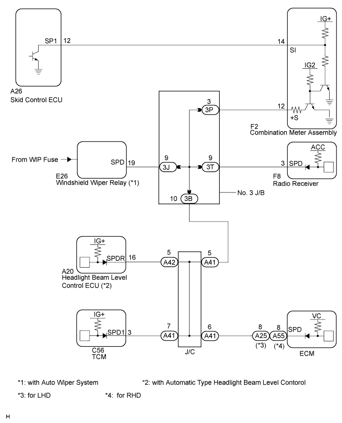
WIRING DIAGRAM
INSPECTION PROCEDURE
| 1.INSPECT SPEEDOMETER (METER OPERATION) |
Drive the vehicle and check if operation of the speedometer in the combination meter is normal.
- HINT:
- The vehicle speed sensor is operating normally if the speedometer display is normal.
| | CHECK SPEEDOMETER CIRCUIT |
|
|
Shift the lever to the neutral position.
Jack up the vehicle.
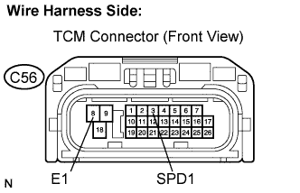
Disconnect the TCM connector.
Turn the ignition switch on.
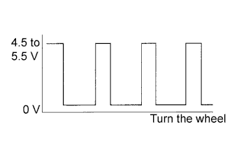
Measure the voltage according to the value(s) in the table below as the wheel is turned slowly.
- Standard:
Tester Connection
| Specified Condition
|
C56-3 (SPD1) - C56-8 (E1)
| Voltage is generated intermittently
|
- HINT:
- The output voltage should fluctuate up and down similarly to the diagram when the wheel is turned slowly.
| | REPAIR OR REPLACE HARNESS OR CONNECTOR |
|
|