Automatic Transaxle System -- Diagnosis System |
| EURO-OBD |
When troubleshooting Europe On-Board Diagnostic (Euro-OBD) vehicles, the vehicle must be connected to an OBD scan tool (complying with ISO 15765-4). Various data output from the vehicle's ECM can then be read.
Euro-OBD regulations require that the vehicle's on-board computer illuminates the Malfunction Indicator Lamp (MIL) on the instrument panel when the computer detects a malfunction in:
The emission control system/components.
The power train control components (which affect vehicle emissions).
The computer.
In addition, the applicable Diagnostic Trouble Codes (DTCs) prescribed by ISO 15765-4 are recorded in the ECM memory.
If the malfunction does not reoccur in 3 consecutive trips, the MIL turns off automatically but the DTCs remain recorded in the ECM memory.
To check DTCs, connect the intelligent tester or OBD scan tool to the Data Link Connector 3 (DLC3) of the vehicle. The scan tool displays DTCs, the freeze frame data and a variety of the engine data.
The DTCs and freeze frame data can be erased with the scan tool (CAMRY_ACV40 RM000000W710GRX.html).
 |
  |
| M-OBD (EXCEPT EUROPEAN SPEC.) |
When troubleshooting Multiplex On-Board Diagnostic (M-OBD) vehicles, the vehicle must be connected to the intelligent tester. Various data output from the ECM can then be read.
OBD regulations require that the vehicle's on-board computer illuminates the MIL on the instrument panel when the computer detects a malfunction in:
The emission control system/components.
The power train control components (which affect vehicle emissions).
The computer.
In addition to, the applicable DTCs are recorded in the ECM memory.
If the malfunction does not reoccur in 3 consecutive trips, the MIL turns off automatically but the DTCs remain recorded in the ECM memory.
|
| NORMAL MODE AND CHECK MODE |
| 2-TRIP DETECTION LOGIC |
When a malfunction is first detected, the malfunction is temporarily stored in the ECM memory (1st trip). If the engine switch is turned off and then turned on again, and the same malfunction is detected again, the MIL will illuminate.
| FREEZE FRAME DATA |
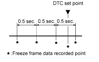
The ECM records vehicle and driving condition information as freeze frame data the moment a DTC is stored. When troubleshooting, freeze frame data can be helpful in determining whether the vehicle was running or stopped, whether the engine was warmed up or not, whether the air/fuel ratio was lean or rich, as well as other data recorded at the time of a malfunction.
The intelligent tester displays freeze frame data recorded at five different points: 1) 3 times before the DTC is set, 2) once when the DTC is set, and 3) once after the DTC is set. The data can be used to simulate the vehicle's condition around the time of the malfunction. The data may be helpful in determining the cause of a malfunction. It may also be helpful in determining whether a DTC is being caused by a temporary malfunction.
 |
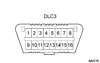
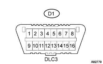
| INSPECT THE DLC3 |
The vehicle's ECM uses ISO 15765-4for communication. The terminal arrangement of the DLC3 complies with ISO 15031-3and matches the ISO 15765-4format.
- Terminals of DLC 3:
Symbol Terminal No. Name Reference Terminal Result Condition SIL 7 Bus "+" line 5 - Signal ground Pulse generation During transmission CG 4 Chassis ground Body ground Below 1 Ω Always SG 5 Signal ground Body ground Below 1 Ω Always BAT 16 Battery positive Body ground 11 to 14 V Always CANH 6 CAN bus line CANL 54 to 69 Ω IG switch OFF* CANH 6 HIGH-level CAN bus line Battery positive 6 kΩ or higher IG switch OFF* CANH 6 HIGH-level CAN bus lineCG CG 200 Ω or higher IG switch OFF* CANL 14 LOW-level CAN bus line Battery positive 6 kΩ or higher IG switch OFF* CANL 14 LOW-level CAN bus line CG 200 Ω or higher IG switch OFF*
- CAUTION:
- *: Before measuring the resistance, leave the vehicle as is for at least 1 minute and do not operate the ignition switch, any other switches or the doors.
- HINT:
- Connect the cable of the intelligent tester to the DLC3, turn the ignition switch to the ON and attempt to use the intelligent tester. If the screen displays a communication error message, a problem exists in the vehicle side or the tester side.
- If the communication is normal when the tool is connected to another vehicle, inspect the DLC3 on the original vehicle.
- If the communication is still impossible when the tool is connected to another vehicle, the problem is probably in the tool itself. Consult the Service Department listed in the tool's instruction manual.
 |
| CHECK BATTERY VOLTAGE |
Measure the battery voltage.
- Battery voltage:
- 11 to 14 V
| CHECK MIL |
Check that the MIL illuminates when turning the ignition switch to the ON position.
- HINT:
- If the MIL does not light up, troubleshoot the combination meter.
When the engine is started, the MIL should go off. If the lamp remains on, it means that the diagnosis system has detected a malfunction or abnormality in the system.