INSTALL UPPER CONSOLE REAR PANEL SUB-ASSEMBLY (for Manual Transaxle)
INSTALL UPPER CONSOLE REAR PANEL SUB-ASSEMBLY (for Automatic Transaxle)
INSTALL FLOOR SHIFT POSITION INDICATOR HOUSING SUB-ASSEMBLY (for Automatic Transaxle)
INSTALL SHIFT LEVER KNOB SUB-ASSEMBLY (for Manual Transaxle)
INSTALL SHIFT LEVER KNOB SUB-ASSEMBLY (for Automatic Transaxle)
Center Airbag Sensor Assembly -- Installation |
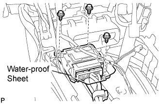
| 1. INSTALL CENTER AIRBAG SENSOR ASSEMBLY |
Check that the ignition switch is off.
Check that the battery negative (-) cable is disconnected.
- CAUTION:
- Wait for 90 seconds after disconnecting the cable to prevent airbag deployment.
Install the center airbag sensor assembly with the 3 bolts.
- Torque:
- 17.5 N*m{179 kgf*cm, 13 ft.*lbf}
- NOTICE:
- If the center airbag sensor assembly has been dropped, or there are any cracks, dents or other defects in the case, bracket or connector, replace it with a new one.
- When installing the center airbag sensor assembly, be careful that the SRS wiring does not interfere with other parts and that it is not pinched between other parts.
 |
Check that there is no looseness in the installation parts of the center airbag sensor assembly.
Connect the holder (with connectors).
Check that the water-proof sheet is properly set.
| 2. INSTALL NO. 1 CONSOLE BOX DUCT (w/ Rear Register Duct) |
Install the No. 1 console box duct with the clip.
 |
| 3. INSTALL NO. 2 CONSOLE BOX INSERT FRONT |
Engage the clip.
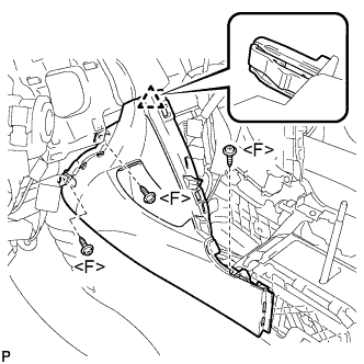 |
Install the No. 2 console box insert front with the 3 screws <F>.
| 4. INSTALL NO. 1 CONSOLE BOX INSERT FRONT |
Engage the clip.
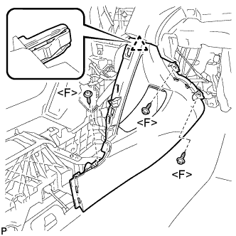 |
Install the No. 1 console box insert front with the 3 screws <F>.
| 5. INSTALL CONSOLE BOX ASSEMBLY |
Install the 2 screws <F>.
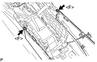 |
Install the console box assembly with the 2 bolts <G>.
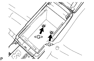 |
| 6. INSTALL CONSOLE BOX CARPET |
Install the console box carpet.
 |
| 7. INSTALL CONSOLE BOX POCKET |
Install the console box pocket.
| 8. INSTALL LOWER INSTRUMENT PANEL SUB-ASSEMBLY |
Engage the 3 claws and 3 clips.
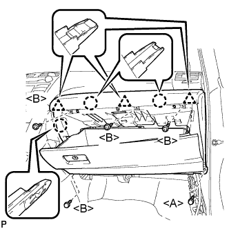 |
Install the 4 screws <B>.
Install the lower instrument panel sub-assembly with the bolt <A>.
| 9. INSTALL INSTRUMENT PANEL NO. 2 UNDER COVER SUB-ASSEMBLY |
Engage the 4 claws and 2 guides and install the instrument panel No. 2 under cover.
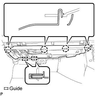 |
| 10. INSTALL COWL SIDE TRIM SUB-ASSEMBLY RH |
- HINT:
- Use the same procedures for the RH side and the LH side.
| 11. INSTALL FRONT DOOR SCUFF PLATE RH |
- HINT:
- Use the same procedures for the RH side and the LH side.
| 12. INSTALL LOWER INSTRUMENT PANEL FINISH PANEL LH |
Install the air hose and connect the connector.
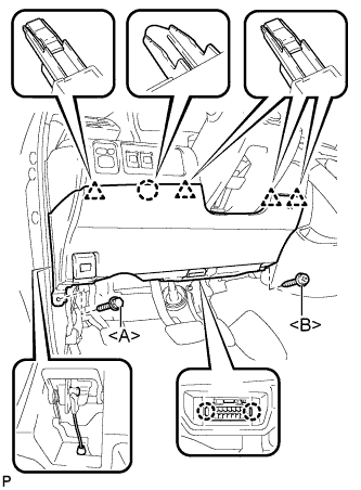 |
Engage the 2 claws and the DLC3.
Engage the claw and the 4 clips.
Instal the lower instrument panel finish panel LH with the screw <B> and bolt <A>.
| 13. INSTALL COWL SIDE TRIM SUB-ASSEMBLY LH |
Engage the 2 clips.
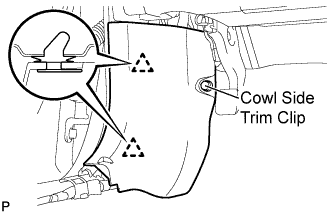 |
Install the cowl side trim sub-assembly LH with the cowl side trim clip.
| 14. INSTALL FRONT DOOR SCUFF PLATE LH |
Engage the 7 claws and 3 clips, then install the front door scuff plate LH.
 |
| 15. INSTALL UPPER CONSOLE PANEL SUB-ASSEMBLY |
Connect each connector.
Engage the 4 claws.
 |
Install the upper console panel sub-assembly with the 2 screws <F>.
| 16. INSTALL UPPER CONSOLE REAR PANEL SUB-ASSEMBLY (for Manual Transaxle) |
Engage the 3 claws and 5 clips to install the upper console rear panel sub-assembly.
 |
| 17. INSTALL UPPER CONSOLE REAR PANEL SUB-ASSEMBLY (for Automatic Transaxle) |
Connect the connector.
 |
Engage the 3 claws and 5 clips to install the upper console rear panel sub-assembly.
| 18. INSTALL UPPER CONSOLE PANEL (for Manual Transaxle) |
Engage the 2 claws and the 5 clips to install the upper console panel as shown in the illustration.
 |
| 19. INSTALL FLOOR SHIFT POSITION INDICATOR HOUSING SUB-ASSEMBLY (for Automatic Transaxle) |
with Seat Heater System:
Connect each connector.
Engage the 6 claws and the 3 clips to install the floor shift position indicator housing sub-assembly.
 |
| 20. INSTALL NO. 2 INSTRUMENT CLUSTER FINISH PANEL GARNISH |
Engage the 2 clips and install the No. 2 instrument cluster finish panel garnish.
 |
| 21. INSTALL NO. 1 INSTRUMENT CLUSTER FINISH PANEL GARNISH |
Engage the 2 clips and install the No. 1 instrument cluster finish panel garnish.
 |
| 22. INSTALL SHIFT LEVER KNOB SUB-ASSEMBLY (for Manual Transaxle) |
Install the shift lever knob sub-assembly.
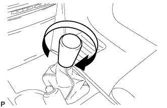 |
| 23. INSTALL SHIFT LEVER KNOB SUB-ASSEMBLY (for Automatic Transaxle) |
Install the shift lever knob sub-assembly.
 |
| 24. CONNECT CABLE TO NEGATIVE BATTERY TERMINAL |
| 25. INSPECT SRS WARNING LIGHT |
Inspect the SRS warning light (CAMRY_ACV40 RM000000XFD0BDX.html).