DESCRIPTION
WIRING DIAGRAM
INSPECTION PROCEDURE
INSPECT FUSE (EFI NO. 1)
CHECK HARNESS AND CONNECTOR
INSPECT BATTERY
CHECK BATTERY TERMINAL
CHECK WHETHER DTC OUTPUT RECURS
DESCRIPTION
The battery supplies electricity to the ECM even when the ignition switch is off. This power allows the ECM to store data such as DTC history, freeze frame data and fuel trim values. If the battery voltage falls below a minimum level, these memories are cleared and the ECM determines that there is a malfunction in the power supply circuit. When the engine is next started, the ECM will illuminate the MIL and set the DTC.DTC No.
| DTC Detection Condition
| Trouble Area
|
P0560
| Open in ECM back-up power source circuit
(1 trip detection logic)
| - Open in back-up power source circuit
- ECM
|
- HINT:
- If DTC P0560 is set, the ECM does not store other DTCs.
WIRING DIAGRAM
INSPECTION PROCEDURE
- HINT:
- Read freeze frame data using the intelligent tester. The ECM records vehicle and driving condition information as freeze frame data the moment a DTC is stored. When troubleshooting, freeze frame data can be helpful in determining whether the vehicle was running or stopped, whether the engine was warmed up or not, whether the air-fuel ratio was lean or rich, as well as other data recorded at the time of a malfunction (CAMRY_ACV40 RM000000PDS01FX.html).
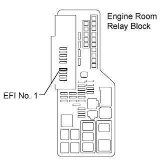
| 1.INSPECT FUSE (EFI NO. 1) |
Remove the EFI No. 1 fuse from the engine room R/B.
Measure the EFI No. 1 fuse resistance.
- Standard resistance:
- Below 1 Ω
Reinstall the EFI No. 1 fuse.
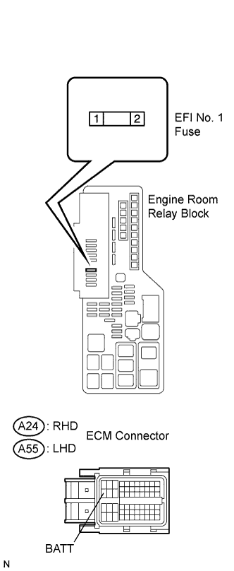
| 2.CHECK HARNESS AND CONNECTOR |
Check the harness and connector between the EFI No. 1 fuse and ECM.
Remove the EFI No. 1 fuse from the engine room R/B.
Disconnect the A24 (RHD) or A55 (LHD) ECM connector.
Measure the resistance between the terminals.
- Standard resistance (Check for open):
- RHD:
Tester Connection
| Specified Condition
|
Engine room R/B EFI No. 1 fuse terminal 2 - BATT (A24-20)
| Below 1 Ω
|
- LHD:
Tester Connection
| Specified Condition
|
Engine room R/B EFI No. 1 fuse terminal 2 - BATT (A55-20)
| Below 1 Ω
|
- Standard resistance (Check for short):
- RHD:
Tester Connection
| Specified Condition
|
Engine room R/B EFI No. 1 fuse terminal 2 or BATT (A24-20) - Body ground
| 10 kΩ or higher
|
- LHD:
Tester Connection
| Specified Condition
|
Engine room R/B EFI No. 1 fuse terminal 2 or BATT (A55-20) - Body ground
| 10 kΩ or higher
|
Reinstall the ECM connector.
Check the harness and the connector between the EFI No. 1 fuse and battery.
Disconnect the negative battery terminal.
Disconnect the positive battery terminal.
Measure the resistance between the terminals.
- Standard resistance:
- Check for open:
Tester Connection
| Specified Condition
|
Battery positive terminal - Engine room R/B EFI No. 1 fuse terminal 1
| Below 1 Ω
|
- Check for short:
Tester Connection
| Specified Condition
|
Battery positive terminal or Engine room R/B EFI No. 1 fuse terminal 1 - Body ground
| 10 kΩ or higher
|
Reconnect the positive battery terminal.
Disconnect the negative battery terminal.
Reinstall the EFI No. 1 fuse.
| | REPAIR OR REPLACE HARNESS OR CONNECTOR |
|
|
Check that the battery is not depleted.
- OK:
- Battery is not depleted.
Check that the battery terminals are not loose or corroded.
- OK:
- Battery terminals are not loose or corroded.
| | REPAIR OR REPLACE BATTERY TERMINAL |
|
|
| 5.CHECK WHETHER DTC OUTPUT RECURS |
Connect the intelligent tester to the DLC3.
Turn the ignition switch to the ON position.
Turn the intelligent tester on.
Clear the DTCs (CAMRY_ACV40 RM000000PDK01VX.html).
Turn the intelligent tester off.
Start the engine and turn the intelligent tester on.
Select the following menu items: Powertrain / Engine / DTC.
Read the DTCs.
- Result:
Display (DTC Output)
| Proceed to
|
P0560
| A
|
No output
| B
|
| | CHECK FOR INTERMITTENT PROBLEMS |
|
|