Dtc P0327 Knock Sensor 1 Circuit Low Input (Bank 1 Or Single Sensor)
DESCRIPTION
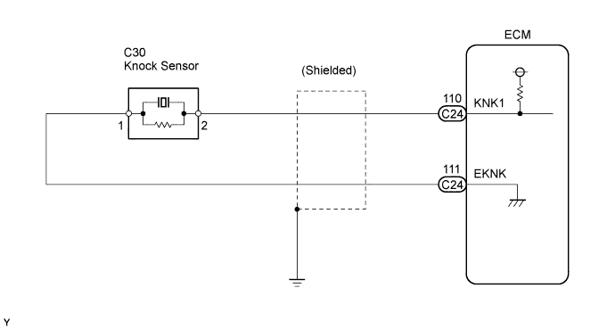
WIRING DIAGRAM
INSPECTION PROCEDURE
READ VALUE USING INTELLIGENT TESTER (KNOCK FEEDBACK VALUE)
CHECK HARNESS AND CONNECTOR (ECM - KNOCK SENSOR)
INSPECT ECM (KNK1 VOLTAGE)
INSPECT KNOCK SENSOR
DTC P0327 Knock Sensor 1 Circuit Low Input (Bank 1 or Single Sensor) |
DTC P0328 Knock Sensor 1 Circuit High Input (Bank 1 or Single Sensor) |
DESCRIPTION
Flat type knock sensors (non-resonant type) have structures that can detect vibrations over a wide band of frequencies: between approximately 6 kHz and 15 kHz. Knock sensors are fitted onto the engine block to detect engine knocking.The knock sensor contains a piezoelectric element which generates a voltage when it becomes deformed.The voltage is generated when the engine block vibrates due to knocking. Any occurrence of engine knocking can be suppressed by delaying the ignition timing.DTC No.
| DTC Detection Condition
| Trouble Area
|
P0327
| Output voltage of knock sensor is 0.5 V or less
(1 trip detection logic)
| - Short in knock sensor circuit
- Knock sensor
- ECM
|
P0328
| Output voltage of knock sensor is 4.5 V or more
(1 trip detection logic)
| - Open in knock sensor circuit
- Knock sensor
- ECM
|
- HINT:
- When any of DTCs P0327 and P0328 are set, the ECM enters fail-safe mode. During fail-safe mode, the ignition timing is delayed to its maximum retardation. Fail-safe mode continues until the ignition switch is turned off.
Reference: Inspection using an oscilloscope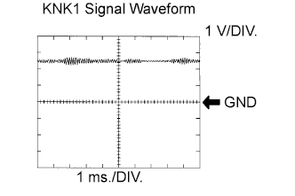 The correct waveform is as shown.
Item
| Content
|
Terminals
| KNK1 - EKNK
|
Equipment Settings
| 1 V/DIV.
1 ms./DIV.
|
Conditions
| Keep engine speed at 4,000 rpm with warm engine
|
WIRING DIAGRAM
INSPECTION PROCEDURE
- HINT:
- Read freeze frame data using the intelligent tester. The ECM records vehicle and driving condition information as freeze frame data the moment a DTC is stored. When troubleshooting, freeze frame data can help determine if the vehicle was moving or stationary, if the engine was warmed up or not, if the air-fuel ratio was lean or rich, and other data from the time the malfunction occurred.
| 1.READ VALUE USING INTELLIGENT TESTER (KNOCK FEEDBACK VALUE) |
Connect the intelligent tester to the DLC3.
Start the engine and turn the tester on.
Warm up the engine.
Select the following menu items: Powertrain / Engine and ECT / Data List / Knock Feedback Value.
Read the values displayed on the tester while driving the vehicle.
- Standard:
- The values change.
- HINT:
Malfunction does not occur
| Knock Feedback Values change
|
Malfunctions occur
| Knock Feedback Values do not change
|
- The knock feedback value change can be confirmed by running the engine with a high load, for example, by activating the air conditioning system and racing the engine.
| OK |
|
|
|
| CHECK FOR INTERMITTENT PROBLEMS |
|
| 2.CHECK HARNESS AND CONNECTOR (ECM - KNOCK SENSOR) |
Disconnect the C24 ECM connector.
Measure the resistance between the terminals.
- Standard resistance:
Tester Connection
| Specified Condition
|
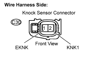
KNK1 (C24-110) - EKNK (C24-111)
| 120 to 280 kΩ at 20°C (68°F)
|
Reconnect the ECM connector.
| 3.INSPECT ECM (KNK1 VOLTAGE) |
Disconnect the C30 knock sensor connector.
Turn the ignition switch to the ON position.
Measure the voltage between the knock sensor terminals.
- Standard voltage:
Tester Connection
| Specified Condition
|
KNK1 (C30-2) - EKNK (C30-1)
| 4.5 to 5.5 V
|
Reconnect the knock sensor connector.
| OK |
|
|
|
| CHECK FOR INTERMITTENT PROBLEMS |
|
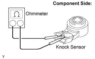
Remove the knock sensor.
Measure the resistance between the terminals.
- Standard resistance:
Tester Connection
| Specified Condition
|
KNK1 (2) - EKNK (1)
| 120 to 280 kΩ at 20°C (68°F)
|
Reinstall the knock sensor.
| OK |
|
|
|
| REPAIR OR REPLACE HARNESS OR CONNECTOR |
|