Dtc P0037 Oxygen Sensor Heater Control Circuit Low (Bank 1 Sensor 2)
DESCRIPTION
WIRING DIAGRAM
INSPECTION PROCEDURE
INSPECT HEATED OXYGEN SENSOR (HEATER RESISTANCE)
CHECK TERMINAL VOLTAGE (+B OF HO2 SENSOR)
INSPECT FUSE (EFI NO. 3)
INSPECT ENGINE ROOM JUNCTION BLOCK
INSPECT FUSE (EFI MAIN)
CHECK HARNESS AND CONNECTOR (HO2 SENSOR - EFI RELAY)
CHECK HARNESS AND CONNECTOR (HO2 SENSOR - ECM)
CHECK WHETHER DTC OUTPUT RECURS
DTC P0037 Oxygen Sensor Heater Control Circuit Low (Bank 1 Sensor 2) |
DTC P0038 Oxygen Sensor Heater Control Circuit High (Bank 1 Sensor 2) |
DTC P0057 Oxygen Sensor Heater Control Circuit Low (Bank 2 Sensor 2) |
DTC P0058 Oxygen Sensor Heater Control Circuit High (Bank 2 Sensor 2) |
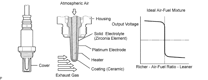
DESCRIPTION
A three-way catalytic converter (TWC) is used in order to convert the carbon monoxide (CO), hydrocarbon (HC), and nitrogen oxide (NOx) into less harmful substances. To allow the TWC to function effectively, it is necessary to keep the air-fuel ratio of the engine near the stoichiometric air-fuel ratio. For the purpose of helping the ECM to deliver accurate air-fuel ratio control, a Heated Oxygen (HO2) sensor is used.The HO2 sensor is located behind the TWC, and detects the oxygen concentration in the exhaust gas. Since the sensor is integrated with the heater that heats the sensing portion, it is possible to detect the oxygen concentration even when the intake air volume is low (the exhaust gas temperature is low).When the air-fuel ratio becomes lean, the oxygen concentration in the exhaust gas becomes rich. The HO2 sensor informs the ECM that the post-TWC air-fuel ratio is lean (low voltage, i.e. less than 0.45 V).Conversely, when the air-fuel ratio is richer than the stoichiometric air-fuel level, the oxygen concentration in the exhaust gas becomes lean. The HO2 sensor informs the ECM that the post-TWC air-fuel ratio is rich (high voltage, i.e. more than 0.45 V). The HO2 sensor has the property of changing its output voltage drastically when the air-fuel ratio is close to the stoichiometric level.The ECM uses the supplementary information from the HO2 sensor to determine whether the air-fuel ratio after the TWC is rich or lean, and adjusts the fuel injection time accordingly. Thus, if the HO2 sensor is working improperly due to internal malfunctions, the ECM is unable to compensate for deviations in the primary air-fuel ratio control.- HINT:
- Sensor 2 refers to the sensor mounted behind the Three-Way Catalytic Converter (TWC) and located far from the engine assembly.
- When any of these DTCs are set, the ECM enters fail-safe mode. The ECM turns off the Heated Oxygen (HO2) Sensor heater in fail-safe mode. Fail-safe mode continues until the ignition switch is turned off.
- The ECM provides a pulse width modulated control circuit to adjust the current through the heater. The HO2 sensor heater circuit uses a relay on the B+ side of the circuit.
DTC No.
| DTC Detection Condition
| Trouble Area
|
P0037
P0057
| Heated Oxygen (HO2) sensor heater current is less than 0.3 A (1 trip detection logic)
| - Open in HO2 sensor heater circuit
- HO2 sensor heater
- Integration relay
- ECM
|
P0038
P0058
| Heated Oxygen (HO2) sensor heater current is more than 3.5 A (1 trip detection logic)
| - Short in HO2 sensor heater circuit
- HO2 sensor heater
- Integration relay
- ECM
|
- HINT:
- Bank 1 refers to the bank that includes cylinder No. 1.
- Bank 2 refers to the bank that does not include cylinder No. 1.
- Sensor 1 refers to the sensor closest to the engine assembly.
- Sensor 2 refers to the sensor farthest away from the engine assembly.
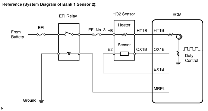
WIRING DIAGRAM
Refer to DTC P0136 (Link).
INSPECTION PROCEDURE
- HINT:
- Read freeze frame data using the intelligent tester. The ECM records vehicle and driving condition information as freeze frame data the moment a DTC is stored. When troubleshooting, freeze frame data can be helpful in determining whether the vehicle was running or stopped, whether the engine was warmed up or not, whether the air-fuel ratio was lean or rich, as well as other data recorded at the time of a malfunction (CAMRY_ACV40 RM000000PDS01FX.html).
| 1.INSPECT HEATED OXYGEN SENSOR (HEATER RESISTANCE) |
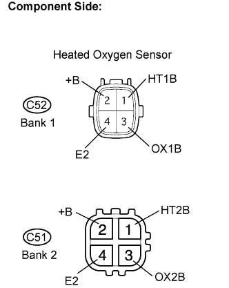
Disconnect the C52 heated oxygen sensor connector (Bank 1 Sensor 2) or C51 heated oxygen sensor connector (Bank 2 Sensor 2).
Measure the resistance according to the value(s) in the table below.
- Standard resistance:
- Bank 1 sensor 2:
Tester Connection
| Condition
| Specified Condition
|
HT1B (1) - +B (2)
| 20°C (68°F)
| 11 to 16 Ω
|
HT1B (1) - E2 (4)
| Always
| 10 kΩ or higher
|
- Bank 2 sensor 2:
Tester Connection
| Condition
| Specified Condition
|
HT2B (1) - +B (2)
| 20°C (68°F)
| 11 to 16 Ω
|
HT2B (1) - E2 (4)
| Always
| 10 kΩ or higher
|
Reconnect the HO2 sensor connector.
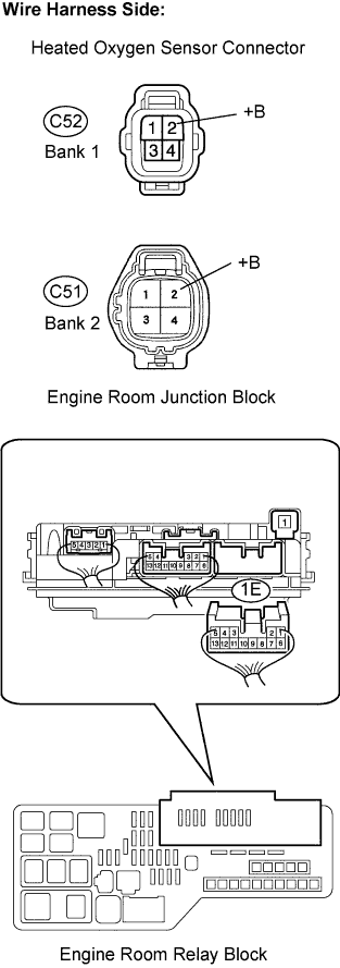
| 2.CHECK TERMINAL VOLTAGE (+B OF HO2 SENSOR) |
Disconnect the C52 heated oxygen sensor connector (Bank 1 Sensor 2) or C51 heated oxygen sensor connector (Bank 2 Sensor 2).
Turn the ignition switch to the ON position.
Measure the voltage between the terminals.
- Standard voltage:
Tester Connection
| Specified Condition
|
+B (C52-2) - Body ground
| 9 to 11 V
|
+B (C51-2) - Body ground
| 9 to 11 V
|
Reconnect the HO2 sensor connector.
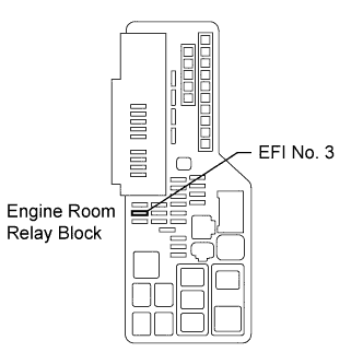
| 3.INSPECT FUSE (EFI NO. 3) |
Remove the EFI No. 3 fuse from the engine room R/B.
Measure the EFI No. 3 fuse resistance.
- Standard resistance:
- Below 1 Ω
Reinstall the EFI No. 3 fuse.
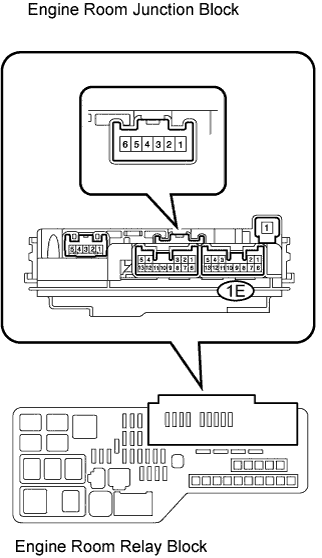
| 4.INSPECT ENGINE ROOM JUNCTION BLOCK |
Remove the engine room junction block from the engine room R/B.
Inspect the EFI relay.
Measure the EFI relay resistance.
- Standard resistance:
Tester Connection
| Specified Condition
|
1E-12 - 1E-6
| 10 kΩ or higher
|
1E-12 - 1E-6
| Below 1 Ω (Apply battery voltage between terminals 1E-9 and 1E-10)
|
Reinstall the engine room junction block.
| | REPLACE ENGINE ROOM JUNCTION BLOCK |
|
|
| 5.INSPECT FUSE (EFI MAIN) |
Remove the EFI MAIN fuse from the engine room R/B.
Measure the EFI MAIN fuse.
- Standard resistance:
- Below 1 Ω
Reinstall the EFI MAIN fuse.
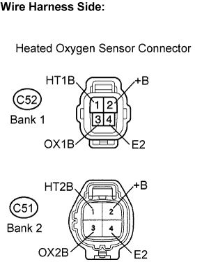
| 6.CHECK HARNESS AND CONNECTOR (HO2 SENSOR - EFI RELAY) |
Disconnect the C52 or C51 HO2 sensor connector.
Remove the engine room junction block from the engine room R/B.
Measure the resistance between the terminals.
- Standard resistance:
- Check for open:
Tester Connection
| Specified Condition
|
+B (C52-2) - 1E-6 (Engine room R/B)
| Below 1 Ω
|
+B (C51-2) - 1E-6 (Engine room R/B)
| Below 1 Ω
|
- Check for short:
Tester Connection
| Specified Condition
|
+B (C52-2) or 1E-6 (Engine room R/B) - Body ground
| 10 kΩ or higher
|
+B (C51-2) or 1E-6 (Engine room R/B) - Body ground
| 10 kΩ or higher
|
Reinstall the engine room junction block.
Reconnect the HO2 sensor connector.
| | REPAIR OR REPLACE HARNESS OR CONNECTOR |
|
|
| OK |
|
|
|
| CHECK ECM POWER SOURCE CIRCUIT |
|
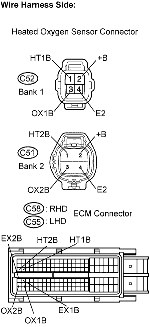
| 7.CHECK HARNESS AND CONNECTOR (HO2 SENSOR - ECM) |
Disconnect the C52 heated oxygen sensor connector (Bank 1 Sensor 2) or C51 heated oxygen sensor connector (Bank 2 Sensor 2).
Turn the ignition switch to the ON position.
Measure the voltage according to the value(s) in the table below.
- Standard voltage:
Terminal Connection
| Specified Condition
|
+B (C52-2) - Body ground
| 9 to 14 V
|
+B (C51-2) - Body ground
| 9 to 14 V
|
Turn the ignition switch off.
Disconnect the C58 (RHD) or C55 (LHD) ECM connector.
Measure the resistance according to the value(s) in the table below.
- Standard resistance (Check for open):
- RHD:
Terminal Connection
| Specified Condition
|
HT1B (C52-1) - HT1B (C58-48)
| Below 1 Ω
|
OX1B (C52-3) - OX1B (C58-88)
| Below 1 Ω
|
E2 (C52-4) - EX1B (C58-65)
| Below 1 Ω
|
HT2B (C51-1) - HT2B (C58-47)
| Below 1 Ω
|
OX2B (C51-3) - OX2B (C58-87)
| Below 1 Ω
|
E2 (C51-4) - EX2B (C58-64)
| Below 1 Ω
|
- LHD:
Terminal Connection
| Specified Condition
|
HT1B (C52-1) - HT1B (C55-48)
| Below 1 Ω
|
OX1B (C52-3) - OX1B (C55-88)
| Below 1 Ω
|
E2 (C52-4) - EX1B (C55-65)
| Below 1 Ω
|
HT2B (C51-1) - HT2B (C55-47)
| Below 1 Ω
|
OX2B (C51-3) - OX2B (C55-87)
| Below 1 Ω
|
E2 (C51-4) - EX2B (C55-64)
| Below 1 Ω
|
- Standard resistance (Check for short):
- RHD:
Terminal Connection
| Specified Condition
|
HT1B (C52-1) or HT1B (C58-48) - Body ground
| 10 kΩ or higher
|
OX1B (C52-3) - OX1B (C58-88) - Body ground
| 10 kΩ or higher
|
E2 (C52-4) or EX1B (C58-65) - Body ground
| 10 kΩ or higher
|
HT2B (C51-1) or HT2B (C58-47) - Body ground
| 10 kΩ or higher
|
OX2B (C51-3) or OX2B (C58-87) - Body ground
| 10 kΩ or higher
|
E2 (C51-4) or EX2B (C58-64) - Body ground
| 10 kΩ or higher
|
- LHD:
Terminal Connection
| Specified Condition
|
HT1B (C52-1) or HT1B (C55-48) - Body ground
| 10 kΩ or higher
|
OX1B (C52-3) - OX1B (C55-88) - Body ground
| 10 kΩ or higher
|
E2 (C52-4) or EX1B (C55-65) - Body ground
| 10 kΩ or higher
|
HT2B (C51-1) or HT2B (C55-47) - Body ground
| 10 kΩ or higher
|
OX2B (C51-3) or OX2B (C55-87) - Body ground
| 10 kΩ or higher
|
E2 (C51-4) or EX2B (C55-64) - Body ground
| 10 kΩ or higher
|
Reconnect the HO2 sensor connector.
Reconnect the ECM connector.
| | REPAIR OR REPLACE HARNESS OR CONNECTOR |
|
|
| 8.CHECK WHETHER DTC OUTPUT RECURS |
Connect the intelligent tester to the DLC3.
Turn the ignition switch to the ON position.
Turn the intelligent tester on.
Clear the DTCs (CAMRY_ACV40 RM000000PDK0D6X.html).
Start the engine.
Allow the engine to idle for 2 minutes.
Select the following menu items: Powertrain / Engine / DTC.
Read the DTCs.
- Result:
Display (DTC Output)
| Proceed To
|
No output
| A
|
P0037, P0038, P0057 and/or P0058
| B
|
| A |
|
|
|
| CHECK FOR INTERMITTENT PROBLEMS |
|