DESCRIPTION
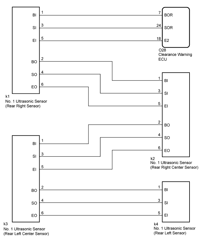
WIRING DIAGRAM
INSPECTION PROCEDURE
CHECK DTC OUTPUT (C1AED)
CHECK HARNESS AND CONNECTOR (CLEARANCE WARNING ECU - REAR RIGHT SENSOR)
CHECK HARNESS AND CONNECTOR (REAR RIGHT SENSOR - REAR RIGHT CENTER SENSOR)
CHECK HARNESS AND CONNECTOR (REAR RIGHT CENTER SENSOR - REAR LEFT CENTER SENSOR)
CHECK HARNESS AND CONNECTOR (REAR LEFT CENTER SENSOR - REAR LEFT SENSOR)
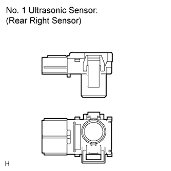
CHECK NO. 1 ULTRASONIC SENSOR (REAR RIGHT SENSOR)
CHECK NO. 1 ULTRASONIC SENSOR (REAR RIGHT CENTER SENSOR)
CHECK NO. 1 ULTRASONIC SENSOR (REAR LEFT CENTER SENSOR)
REPLACE NO. 1 ULTRASONIC SENSOR (REAR RIGHT SENSOR)
CHECK DTC OUTPUT
REPLACE NO. 1 ULTRASONIC SENSOR (REAR RIGHT CENTER SENSOR)
CHECK DTC OUTPUT
REPLACE NO. 1 ULTRASONIC SENSOR (REAR LEFT CENTER SENSOR)
CHECK DTC OUTPUT
REPLACE NO. 1 ULTRASONIC SENSOR (REAR LEFT SENSOR)
CHECK DTC OUTPUT
DTC C1AED Rear Sensor Communication Malfunction |
DESCRIPTION
This DTC is stored when there is an open or short circuit in the communication line between the rear sensors and the ECU, or when there is a malfunction in a rear sensor.DTC No.
| DTC Detection Condition
| Trouble Area
|
C1AED
| An open or short circuit in the communication line between the rear sensors and ECU or a malfunction in a rear sensor during initialization mode after the ignition switch is turned to ON.
| - Rear ultrasonic sensor circuit
- Clearance warning ECU
|
WIRING DIAGRAM
INSPECTION PROCEDURE
| 1.CHECK DTC OUTPUT (C1AED) |
Check for DTCs (CAMRY_ACV40 RM000000VKU01FX.html).
Clear the DTCs (CAMRY_ACV40 RM000000VKU01FX.html).
Recheck for DTCs (CAMRY_ACV40 RM000000VKU01FX.html).
- Result:
Result
| Proceed to
|
DTC C1AED is output
| A
|
No DTC is output
| B
|
| 2.CHECK HARNESS AND CONNECTOR (CLEARANCE WARNING ECU - REAR RIGHT SENSOR) |
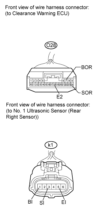
Disconnect the O28connector from the clearance warning ECU.
Disconnect the k1 connector from the No. 1 ultrasonic sensor.
Measure the resistance according to the value(s) in the table below.
- Standard Resistance:
Tester Connection
| Condition
| Specified Condition
|
O28-7 (BOR) - k1-1 (BI)
| Always
| Below 1 Ω
|
O28-24 (SOR) - k1-3 (SI)
|
O28-18 (E2) - k1-5 (EI)
|
O28-7 (BOR) - Body ground
| 10 kΩ or higher
|
O28-24 (SOR) - Body ground
|
O28-18 (E2) - Body ground
|
| | REPAIR OR REPLACE HARNESS OR CONNECTOR |
|
|
| 3.CHECK HARNESS AND CONNECTOR (REAR RIGHT SENSOR - REAR RIGHT CENTER SENSOR) |
Disconnect the k1 and k2 connectors from the No. 1 ultrasonic sensors.
Measure the resistance according to the value(s) in the table below.
- Standard Resistance:
Tester Connection
| Condition
| Specified Condition
|
k1-2 (BO) - k2-1 (BI)
| Always
| Below 1 Ω
|
k1-4 (SO) - k2-3 (SI)
|
k1-6 (EO) - k2-5 (EI)
|
k1-2 (BO) - Body ground
| 10 kΩ or higher
|
k1-4 (SO) - Body ground
|
k1-6 (EO) - Body ground
|
| | REPAIR OR REPLACE HARNESS OR CONNECTOR |
|
|
| 4.CHECK HARNESS AND CONNECTOR (REAR RIGHT CENTER SENSOR - REAR LEFT CENTER SENSOR) |
Disconnect the k2 and k3 connectors from the No. 1 ultrasonic sensors.
Measure the resistance according to the value(s) in the table below.
- Standard Resistance:
Tester Connection
| Condition
| Specified Condition
|
k2-2 (BO) - k3-1 (BI)
| Always
| Below 1 Ω
|
k2-4 (SO) - k3-3 (SI)
|
k2-6 (EO) - k3-5 (EI)
|
k2-2 (BO) - Body ground
| 10 kΩ or higher
|
k2-4 (SO) - Body ground
|
k2-6 (EO) - Body ground
|
| | REPAIR OR REPLACE HARNESS OR CONNECTOR |
|
|
| 5.CHECK HARNESS AND CONNECTOR (REAR LEFT CENTER SENSOR - REAR LEFT SENSOR) |
Disconnect the k3 and k4 connectors from the No. 1 ultrasonic sensors.
Measure the resistance according to the value(s) in the table below.
- Standard Resistance:
Tester Connection
| Condition
| Specified Condition
|
k3-2 (BO) - k4-1 (BI)
| Always
| Below 1 Ω
|
k3-4 (SO) - k4-3 (SI)
|
k3-6 (EO) - k4-5 (EI)
|
k3-2 (BO) - Body ground
| 10 kΩ or higher
|
k3-4 (SO) - Body ground
|
k3-6 (EO) - Body ground
|
| | REPAIR OR REPLACE HARNESS OR CONNECTOR |
|
|
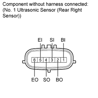
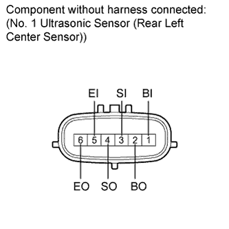
| 6.CHECK NO. 1 ULTRASONIC SENSOR (REAR RIGHT SENSOR) |
Remove the No. 1 ultrasonic sensor (rear right sensor) (CAMRY_ACV40 RM000001PYF01PX.html).
Measure the resistance according to the value(s) in the table below.
- Standard Resistance:
Tester Connection
| Condition
| Specified Condition
|
1 (BI) - 5 (EI)
| Always
| 10 kΩ or higher
|
1 (BI) - 2 (BO)
| Always
| 10 kΩ or higher
|
3 (SI) - 4 (SO)
| Always
| Below 1 Ω
|
5 (EI) - 6 (EO)
| Always
| Below 1 Ω
|
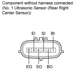
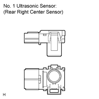
| 7.CHECK NO. 1 ULTRASONIC SENSOR (REAR RIGHT CENTER SENSOR) |
Remove the No. 1 ultrasonic sensor (rear right center sensor) (CAMRY_ACV40 RM000001PYF01PX.html).
Measure the resistance according to the value(s) in the table below.
- Standard Resistance:
Tester Connection
| Condition
| Specified Condition
|
1 (BI) - 5 (EI)
| Always
| 10 kΩ or higher
|
1 (BI) - 2 (BO)
| Always
| 10 kΩ or higher
|
3 (SI) - 4 (SO)
| Always
| Below 1 Ω
|
5 (EI) - 6 (EO)
| Always
| Below 1 Ω
|
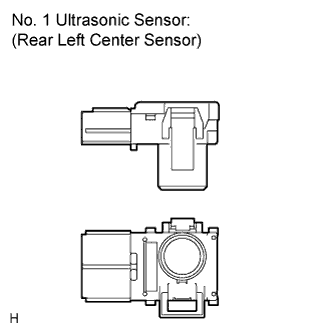
| 8.CHECK NO. 1 ULTRASONIC SENSOR (REAR LEFT CENTER SENSOR) |
Remove the No. 1 ultrasonic sensor (rear left center sensor) (CAMRY_ACV40 RM000001PYF01PX.html).
Measure the resistance according to the value(s) in the table below.
- Standard Resistance:
Tester Connection
| Condition
| Specified Condition
|
1 (BI) - 5 (EI)
| Always
| 10 kΩ or higher
|
1 (BI) - 2 (BO)
| Always
| 10 kΩ or higher
|
3 (SI) - 4 (SO)
| Always
| Below 1 Ω
|
5 (EI) - 6 (EO)
| Always
| Below 1 Ω
|
| 9.REPLACE NO. 1 ULTRASONIC SENSOR (REAR RIGHT SENSOR) |
Replace the No. 1 ultrasonic sensor (rear left sensor) with a normally functioning sensor (CAMRY_ACV40 RM000001PYF01PX.html).
- HINT:
- All of the sensors are interchangeable. To confirm whether a sensor is functioning normally, switch it with a known good sensor from the other end of the vehicle.
Clear the DTCs (CAMRY_ACV40 RM000000VKU01FX.html).
Check for DTCs (CAMRY_ACV40 RM000000VKU01FX.html).
- Result:
Result
| Proceed to
|
DTC C1AED is output
| A
|
No DTC is output
| B
|
| | END (REAR RIGHT SENSOR WAS DEFECTIVE) |
|
|
| 11.REPLACE NO. 1 ULTRASONIC SENSOR (REAR RIGHT CENTER SENSOR) |
Replace the No. 1 ultrasonic sensor (rear left center sensor) with a normally functioning sensor (CAMRY_ACV40 RM000001PYF01PX.html).
- HINT:
- All of the sensors are interchangeable. To confirm whether a sensor is functioning normally, switch it with a known good sensor from the other end of the vehicle.
Clear the DTCs (CAMRY_ACV40 RM000000VKU01FX.html).
Check for DTCs (CAMRY_ACV40 RM000000VKU01FX.html).
- Result:
Result
| Proceed to
|
DTC C1AED is output
| A
|
No DTC is output
| B
|
| | END (REAR RIGHT CENTER SENSOR WAS DEFECTIVE) |
|
|
| 13.REPLACE NO. 1 ULTRASONIC SENSOR (REAR LEFT CENTER SENSOR) |
Replace the No. 1 ultrasonic sensor (rear right center sensor) with a normally functioning sensor (CAMRY_ACV40 RM000001PYF01PX.html).
- HINT:
- All of the sensors are interchangeable. To confirm whether a sensor is functioning normally, switch it with a known good sensor from the other end of the vehicle.
Clear the DTCs (CAMRY_ACV40 RM000000VKU01FX.html).
Check for DTCs (CAMRY_ACV40 RM000000VKU01FX.html).
- Result:
Result
| Proceed to
|
DTC C1AED is output
| A
|
No DTC is output
| B
|
| | END (REAR LEFT CENTER SENSOR WAS DEFECTIVE) |
|
|
| 15.REPLACE NO. 1 ULTRASONIC SENSOR (REAR LEFT SENSOR) |
Replace the No. 1 ultrasonic sensor (rear right sensor) with a normally functioning sensor (CAMRY_ACV40 RM000001PYF01PX.html).
- HINT:
- All of the sensors are interchangeable. To confirm whether a sensor is functioning normally, switch it with a known good sensor from the other end of the vehicle.
Clear the DTCs (CAMRY_ACV40 RM000000VKU01FX.html).
Check for DTCs (CAMRY_ACV40 RM000000VKU01FX.html).
- Result:
Result
| Proceed to
|
DTC C1AED is output
| A
|
No DTC is output
| B
|
| | END (REAR LEFT SENSOR WAS DEFECTIVE) |
|
|