Dtc B2283 Vehicle Speed Sensor Malfunction
DESCRIPTION
WIRING DIAGRAM
INSPECTION PROCEDURE
CHECK DTC OUTPUT (ENTRY AND START SYSTEM)
CHECK OPERATION OF SPEEDOMETER
CHECK DTC OUTPUT (BRAKE CONTROL)
CHECK HARNESS AND CONNECTOR (SKID CONTROL ECU - COMBINATION METER)
INSPECT COMBINATION METER (SPEED SIGNAL)
DTC B2283 Vehicle Speed Sensor Malfunction |
DESCRIPTION
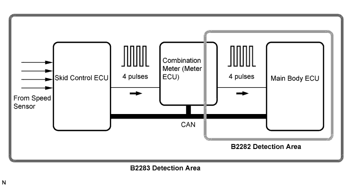
The skid control ECU converts these signals into 4-pulse signals and sends them to the combination meter. After this signal is converted into a more precise rectangular waveform by the waveform shaping circuit inside the combination meter, it is then transmitted to the main body ECU. The main body ECU determines the vehicle speed based on the frequency of these pulse signals.- HINT:
- When the main body ECU is replaced with a new one and the negative (-) battery terminal is connected, the power source mode becomes the IG-ON mode. When the battery is removed and reinstalled, the power source mode that was selected when the battery was removed is restored.
- After the main body ECU is replaced, perform the registration procedures for the engine immobiliser system.
DTC No.
| DTC Detection Condition
| Trouble Area
|
B2283
| When both conditions below are met:
- Over-deceleration in vehicle speed
- Vehicle speed and engine speed do not match
| - B2282 detection area
- Combination meter
- Speed sensor
- Skid control ECU
- Main body ECU
- Wire harness or connector
|
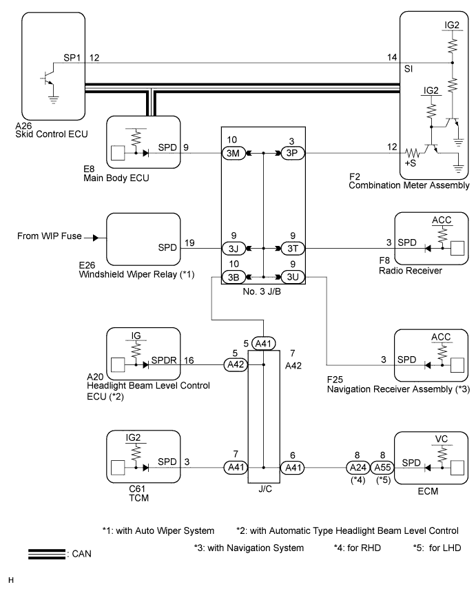
WIRING DIAGRAM
INSPECTION PROCEDURE
| 1.CHECK DTC OUTPUT (ENTRY AND START SYSTEM) |
Clear the DTCs (CAMRY_ACV40 RM000000YEH05QX.html).
After all DTCs are cleared, check if the trouble occurs again 320 seconds after the engine switch is turned on (IG).
Check for DTC B2282 and DTC B2283.
- Result:
Display (DTC output)
| Proceed to
|
"DTC B2283" only
| A
|
"DTC B2283" and "DTC B2282"
| B
|
No DTC
| C
|
- HINT:
- If DTC B2282 and DTC B2283 are output, perform troubleshooting for DTC B2282 first (CAMRY_ACV40 RM000000XEV05PX.html).
| 2.CHECK OPERATION OF SPEEDOMETER |
Drive the vehicle and check if the function of the speedometer in the combination meter is normal.
- OK:
- Actual vehicle speed and the speed indicated on the speedometer are the same.
- HINT:
- The vehicle speed sensor is functioning normally when the indication on the speedometer is normal.
- The meter CPU receives vehicle speed signals from the skid control ECU via the CAN communication lines. The vehicle speed sensor detects the voltage that varies according to the vehicle speed. The skid control ECU supplies power to the vehicle speed sensor. The skid control ECU detects vehicle speed signals based on the pulses of the voltage.
| 3.CHECK DTC OUTPUT (BRAKE CONTROL) |
Delete the DTCs (CAMRY_ACV40 RM000000YEH05QX.html).
Check for DTCs (for w/o VSC: CAMRY_ACV40 RM000001JB800LX.html) (for w/ VSC: CAMRY_ACV40 RM000000XHV04YX.html).
- OK:
- DTC is not output.
| | GO TO BRAKE CONTROL SYSTEM |
|
|
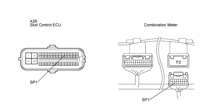
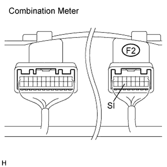
| 4.CHECK HARNESS AND CONNECTOR (SKID CONTROL ECU - COMBINATION METER) |
Disconnect the F2 meter connector.
Disconnect the skid control ECU connector.
Measure the resistance according to the value(s) in the table below.
- Standard Resistance:
Tester Connection)
| Condition
| Specified Condition
|
A26-12 (SP1) - F2-14 (SI)
| Always
| Below 1 Ω
|
A26-12 (SP1) or F2-14 (SI) - Body ground
| Always
| 10 kΩ or higher
|
| | REPAIR OR REPLACE HARNESS OR CONNECTOR |
|
|
| 5.INSPECT COMBINATION METER (SPEED SIGNAL) |
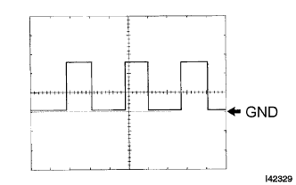
Check the input signal waveform.
Reconnect the connectors.
Remove the combination meter assembly with the connector(s) still connected.
Connect an oscilloscope to terminal F2-14 (SI) and body ground.
Turn the engine switch on (IG).
Turn the wheel slowly.
Check the signal waveform according to the condition(s) in the table below.
Item
| Condition
|
Tool setting
| 5 V/DIV., 10 ms./DIV.
|
Vehicle condition
| Driving at approx. 20 km/h (12 mph)
|
- OK:
- The waveform is displayed as shown in the illustration.
- HINT:
- As the vehicle speed increases, the cycle of the signal waveform narrows.
| OK |
|
|
|
| REPLACE COMBINATION METER |
|