Dtc B2282 Vehicle Speed Signal Malfunction
DESCRIPTION
WIRING DIAGRAM
INSPECTION PROCEDURE
CHECK CAN COMMUNICATION SYSTEM
CHECK SPEEDOMETER OPERATION
READ VALUE USING INTELLIGENT TESTER
CHECK HARNESS AND CONNECTOR (MAIN BODY ECU - COMBINATION METER ASSEMBLY)
INSPECT COMBINATION METER ASSEMBLY (SPEED SIGNAL)
CHECK HARNESS AND CONNECTOR (JUNCTION BLOCK - MAIN BODY ECU)
CHECK HARNESS AND CONNECTOR (JUNCTION BLOCK - COMBINATION METER ASSEMBLY)
DTC B2282 Vehicle Speed Signal Malfunction |
DESCRIPTION
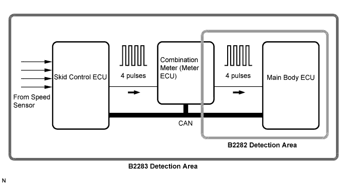
The main body ECU and the combination meter are connected by a cable and the CAN. DTC B2282 is output when: 1) the cable information and CAN information are inconsistent; and 2) a malfunction is detected between the vehicle speed sensor and combination meter.- HINT:
- When the main body ECU is replaced with a new one and the negative (-) battery terminal is connected, the power source mode becomes the IG-ON mode. When the battery is removed and reinstalled, the power source mode that was selected when the battery was removed is restored.
- After the main body ECU is replaced, perform the registration procedures for the engine immobiliser system.
DTC No.
| DTC Detection Condition
| Trouble Area
|
B2282
| When both conditions below are met:
- Cable information and CAN information between the main body ECU and the combination meter are inconsistent
- Malfunction is detected between the vehicle speed sensor and the combination meter
| - CAN communication system
- Combination meter system
- Main body ECU
- Wire harness or connector
|
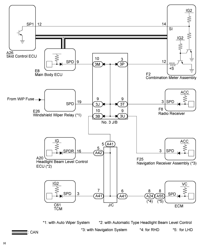
WIRING DIAGRAM
- HINT:
- A voltage of 12 V or 5 V is output from each ECU and then input to the combination meter. The signal is changed to a pulse signal at the transistor in the combination meter. Each ECU controls the respective system based on the pulse signal.
- If a short occurs in an ECU, all systems in the diagram above will not operate normally.
INSPECTION PROCEDURE
| 1.CHECK CAN COMMUNICATION SYSTEM |
Check if CAN communication DTCs are output (for LHD: CAMRY_ACV40 RM000000WI605LX.html) (for RHD: CAMRY_ACV40 RM000000WI605KX.html).
- HINT:
- If any DTCs for CAN communication system malfunction are output, inspect those DTCs first.
- Result:
Result
| Proceed to
|
CAN communication DTC is not output.
| A
|
CAN communication DTC is output (for LHD).
| B
|
CAN communication DTC is output (for RHD).
| C
|
| 2.CHECK SPEEDOMETER OPERATION |
Connect the intelligent tester to the DLC3.
Turn the engine switch on (IG).
Turn the intelligent tester on.
Enter the following menus: Body / Combination Meter / Data List.
Read the Data List according to the display on the intelligent tester.
Combination MeterTester Display
| Measurement Item/Range
| Normal Condition
| Diagnostic Note
|
Vehicle Speed Meter
| Vehicle speed/Min.: 0, Max.: 255
| Almost same as actual speed (When driving)
| -
|
| 3.READ VALUE USING INTELLIGENT TESTER |
Enter the following menus: Body / Body / Data List.
Read the Data List according to the display on the intelligent tester.
BodyTester Display
| Measurement Item/Range
| Normal Condition
| Diagnostic Note
|
Vehicle speed signal
| Vehicle speed signal/Stop or Run
| Stop: Vehicle stopped
Run: Vehicle running
| -
|
- OK:
- Stop (vehicle is sopped) and Run (vehicle is running) appear on the screen.
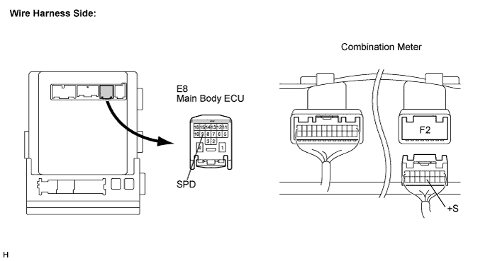
| 4.CHECK HARNESS AND CONNECTOR (MAIN BODY ECU - COMBINATION METER ASSEMBLY) |
Disconnect the E8 ECU connector.
Disconnect the F2 meter connector.
Measure the resistance according to the value(s) in the table below.
- Standard Resistance:
Tester Connection
| Condition
| Specified Condition
|
E8-9 (SPD) - F2-12 (+S)
| Always
| Below 1Ω
|
| 5.INSPECT COMBINATION METER ASSEMBLY (SPEED SIGNAL) |
Remove the combination meter assembly (CAMRY_ACV40 RM0000024D701JX.html).
Reconnect the F15 connector to the combination meter assembly.
Reconnect the E8 connector to the main body ECU.
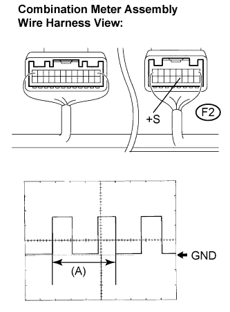
Connect an oscilloscope to terminal F15-3 (SPD) and body ground.
Turn the engine switch on (IG).
Turn the wheel slowly.
Check the signal waveform according to the condition(s) in the table below.
Item
| Condition
|
Tool setting
| 5 V/DIV., 10 ms./DIV.
|
Vehicle condition
| Driving at approx. 20 km/h (12 mph)
|
- OK:
- The waveform is displayed as shown in the illustration.
- HINT:
- When the system is functioning normally, one wheel revolution generates 4 pulses. As the vehicle speed increase, the width indicated by (A) in the illustration narrows.
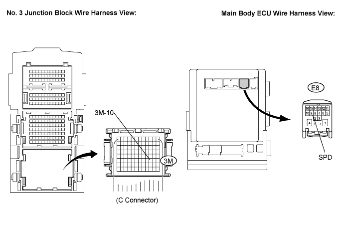
| 6.CHECK HARNESS AND CONNECTOR (JUNCTION BLOCK - MAIN BODY ECU) |
Disconnect the 3M connector from the No. 3 junction block.
Measure the resistance according to the value(s) in the tale below.
- Standard Resistance:
Tester Connection
| Condition
| Specified Condition
|
3M-10 - E8-9 (SPD)
| Always
| Below 1 Ω
|
3M-10 - Body ground
| Always
| 10 kΩ or higher
|
- HINT:
- If the result of the inspection for a short circuit is not as specified, there may be a short in the ECU.
| | REPAIR OR REPLACE HARNESS OR CONNECTOR (JUNCTION BLOCK - MAIN BODY ECU) |
|
|
| 7.CHECK HARNESS AND CONNECTOR (JUNCTION BLOCK - COMBINATION METER ASSEMBLY) |
Disconnect the 3P connector from the No. 3 junction block.
Measure the resistance according to the value(s) in the table below.
- Standard Resistance:
Tester Connection
| Condition
| Specified Condition
|
3P-3 - F2-12 (+S)
| Always
| Below 1 Ω
|
3P-3 - Body ground
| Always
| 10 kΩ or higher
|
| | REPAIR OR REPLACE HARNESS OR CONNECTOR (JUNCTION BLOCK - COMBINATION METER ASSEMBLY) |
|
|