Anti-Lock Brake System Brake Warning Light Remains On
Brake. Camry. Acv40 Gsv40
DESCRIPTION
WIRING DIAGRAM
INSPECTION PROCEDURE
CHECK DTC
INSPECT CAN COMMUNICATION SYSTEM
CHECK IF SKID CONTROL ECU CONNECTOR SECURELY CONNECTED
CHECK BATTERY
INSPECT SKID CONTROL ECU CONNECTOR (IG1 TERMINAL VOLTAGE)
INSPECT SKID CONTROL ECU CONNECTOR (GND TERMINAL CONTINUITY)
INSPECT PARKING BRAKE SWITCH
CHECK HARNESS AND CONNECTOR (MAIN BODY ECU TO PARKING BRAKE SWITCH)
INSPECT BRAKE FLUID LEVEL WARNING SWITCH ASSEMBLY
CHECK HARNESS AND CONNECTOR (BRAKE FLUID LEVEL WARNING SWITCH TO COMBINATION METER)
INSPECT COMBINATION METER ASSEMBLY
ANTI-LOCK BRAKE SYSTEM - Brake Warning Light Remains ON |
DESCRIPTION
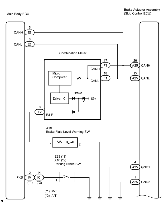
The skid control ECU sends the indicator signals to the combination meter assembly via the CAN communication system.If any of the following is detected, the brake warning light remains on:- The skid control ECU connector is disconnected from the skid control ECU.
- The brake fluid level is insufficient.
- The parking brake is applied.
- EBD operation is not possible.
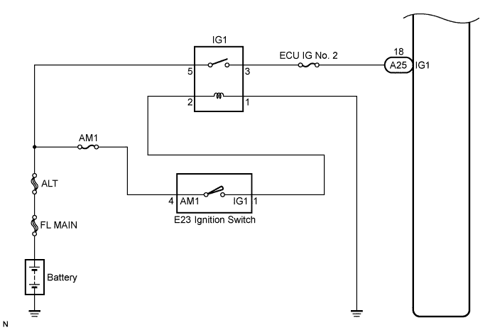
WIRING DIAGRAM
INSPECTION PROCEDURE
- HINT:
- Check the condition of each related circuit connector before troubleshooting (CAMRY_ACV40 RM000000UZ301ZX.html).
Check if an ABS DTC is output (CAMRY_ACV40 RM000001JB8003X.html).
- Result:
Condition
| Proceed to
|
CAN communication system DTC is not output
| A
|
CAN communication system DTC is output
| B
|
| 2.INSPECT CAN COMMUNICATION SYSTEM |
Check if a CAN communication system DTC is output (CAMRY_ACV40 RM000001JB8003X.html).
- Result:
Condition
| Proceed to
|
DTC is not output
| A
|
DTC is output
| B
|
| 3.CHECK IF SKID CONTROL ECU CONNECTOR SECURELY CONNECTED |
Check if the skid control ECU connector is connected securely.
- OK:
- The connector should be securely connected.
| | CONNECT CONNECTOR TO ECU CORRECTLY |
|
|
Check the battery voltage.
- Standard voltage:
- 11 to 14 V
| 5.INSPECT SKID CONTROL ECU CONNECTOR (IG1 TERMINAL VOLTAGE) |
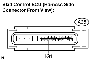
Disconnect the skid control ECU connector.
Turn the ignition switch to the ON position.
Measure the voltage according to the value(s) in the table below.
- Standard voltage:
Tester Connection
| Condition
| Specified Condition
|
A25-18 (IG1) - Body ground
| Ignition switch on
| 10 to 14 V
|
| | REPAIR OR REPLACE HARNESS OR CONNECTOR (IG1 CIRCUIT) |
|
|
| 6.INSPECT SKID CONTROL ECU CONNECTOR (GND TERMINAL CONTINUITY) |
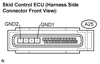
Measure the resistance according to the value(s) in the table below.
- Standard resistance:
Tester Connection
| Specified Condition
|
A25-4 (GND1) - Body ground
| Below 1 Ω
|
A25-1 (GND2) - Body ground
| Below 1 Ω
|
| | REPAIR OR REPLACE HARNESS OR CONNECTOR (GND CIRCUIT) |
|
|
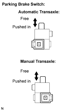
| 7.INSPECT PARKING BRAKE SWITCH |
Remove the parking brake switch.
Disconnect the parking brake switch connector.
Measure the resistance according to the value(s) in the table below.
- Standard resistance:
Automatic TransaxleTester Connection
| Condition
| Specified Condition
|
(A18-1) - Ground part
| Free
| Below 1 Ω
|
(A18-1) - Ground part
| Pushed in
| 10 kΩ or higher
|
Manual TransaxleTester Connection
| Condition
| Specified Condition
|
(E33-1) - Ground part
| Free
| Below 1 Ω
|
(E33-1) - Ground part
| Pushed in
| 10 kΩ or higher
|
| | REPLACE PARKING BRAKE SWITCH |
|
|
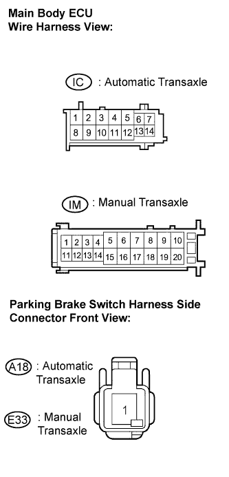
| 8.CHECK HARNESS AND CONNECTOR (MAIN BODY ECU TO PARKING BRAKE SWITCH) |
Disconnect the main body ECU connector.
Measure the resistance according to the value(s) in the table below.
- Standard resistance:
- Automatic Transaxle:
Tester Connection
| Specified Condition
|
IC-14 - A18-1 (PKB)
| Below 1 Ω
|
A18-1 (PKB) - Body ground
| 10 kΩ or higher
|
- Manual Transaxle:
Tester Connection
| Specified Condition
|
IM-2 (PKB) - E33-1 (PKB)
| Below 1 Ω
|
E33-1 (PKB) - Body ground
| 10 kΩ or higher
|
Connect the connector.
| | REPAIR OR REPLACE HARNESS OR CONNECTOR (MAIN BODY ECU TO PARKING BRAKE SWITCH) |
|
|
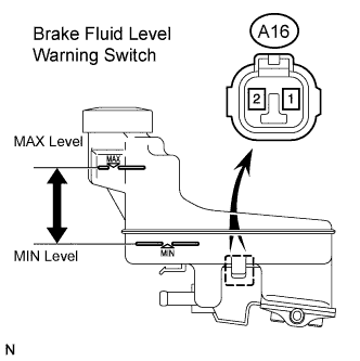
| 9.INSPECT BRAKE FLUID LEVEL WARNING SWITCH ASSEMBLY |
Remove the reservoir tank cap.
Disconnect the brake fluid level warning switch connector.
Measure the resistance according to the value(s) in the table below.
- HINT:
- A float is located inside the reservoir.
- Its position can be changed by increasing or decreasing the level of brake fluid.
- Standard resistance:
Tester Connection
| Condition
| Specified Condition
|
(A16-1) - (A16-2)
| Float UP
| 10 kΩ or higher
(No Continuity)
|
(A16-1) - (A16-2)
| Float DOWN
| Below 1 Ω
(Continuity)
|
- HINT:
- If there is no problem after finishing the above check, adjust the brake fluid level to the MAX level.
| | REPLACE BRAKE MASTER CYLINDER RESERVOIR SUB-ASSEMBLY (BRAKE FLUID LEVEL WARNING SWITCH) |
|
|
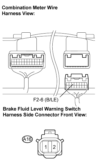
| 10.CHECK HARNESS AND CONNECTOR (BRAKE FLUID LEVEL WARNING SWITCH TO COMBINATION METER) |
Disconnect the combination meter assembly connector.
Measure the resistance according to the value(s) in the table below.
- Standard resistance:
Tester Connection
| Specified Condition
|
A16-1 - F2-6 (B/LE)
| Below 1 Ω
|
F2-6 (B/LE) - Body ground
| 10 kΩ or higher
|
A16-2 - Body ground
| Below 1 Ω
|
Connect the connector.
| | REPAIR OR REPLACE HARNESS OR CONNECTOR (BRAKE FLUID LEVEL WARNING SWITCH TO COMBINATION METER) |
|
|
| 11.INSPECT COMBINATION METER ASSEMBLY |
Connect the intelligent tester to the DLC3.
Select the "Active Test" on the tester (CAMRY_ACV40 RM000001JBA003X.html).
Active Test: ABSTester Display
| Test Part/Control Range
| Diagnostic Note
|
Brake Warning Light
| Turn brake warning light ON / OFF
| Observe combination meter
|
Check the ABS warning light operation.
- OK:
- The BRAKE warning light turns on or off in accordance with the intelligent tester.
- Result:
Condition
| Proceed to
|
OK
| A
|
OK (When troubleshooting in accordance with the PROBLEM SYMPTOMS TABLE)
| B
|
NG
| C
|