DESCRIPTION
WIRING DIAGRAM
INSPECTION PROCEDURE
INSPECT INTEGRATION RELAY (INTEGRATION RELAY - BODY GROUND)
INSPECT INTEGRATION RELAY (EFI MAIN RELAY)
CHECK WIRE HARNESS (+B AND MREL CIRCUIT)
CHECK WIRE HARNESS (ECM - BODY GROUND)
INSPECT ECM (IGSW VOLTAGE)
INSPECT FUSE (IGN, G2)
INSPECT IG2 RELAY
CHECK WIRE HARNESS (ECM - ENGINE ROOM NO. 1 RELAY BLOCK)
CHECK WIRE HARNESS (MAIN BODY ECU - ENGINE ROOM NO. 1 RELAY BLOCK)
CHECK WIRE HARNESS (IGNITION SWITCH - ENGINE ROOM NO. 1 RELAY BLOCK)
INSPECT IGNITION SWITCH ASSEMBLY
ECD SYSTEM - ECM Power Source Circuit |
DESCRIPTION
When the ignition switch is turned on (IG), the battery voltage is applied to terminal IGSW of the ECM. The ECM "MREL" output signal causes a current to flow to the coil, closing the contacts of the MAIN relay and supplying power to terminal +B of the ECM.
WIRING DIAGRAM
INSPECTION PROCEDURE
- ПРИМЕЧАНИЕ:
- After replacing the ECM, the new ECM needs registration (see page RAV4_ACA30 RM000000TJ4007X.html) and initialization (see page RAV4_ACA30 RM000000TIN007X.html).
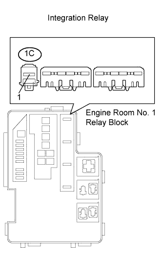
| 1.INSPECT INTEGRATION RELAY (INTEGRATION RELAY - BODY GROUND) |
Remove the integration relay from the engine room No. 1 relay block.
Measure the voltage of the terminal of the integration relay and body ground.
- Standard voltage:
Tester Connection
| Specified Condition
|
1C-1 - Body ground
| 9 to 14 V
|
Reinstall the integration relay.
| | REPAIR OR REPLACE HARNESS AND CONNECTOR |
|
|
| 2.INSPECT INTEGRATION RELAY (EFI MAIN RELAY) |
Remove the integration relay from the engine room No. 1 relay block.
Inspect the EFI MAIN fuse.
Remove the EFI MAIN fuse from the integration relay.
Measure the EFI MAIN fuse resistance.
- Standard resistance:
- Below 1 Ω
Reinstall the EFI MAIN fuse.
Inspect the EFI MAIN relay.
Measure the EFI MAIN relay resistance.
- Standard resistance:
Tester Connection
| Specified Condition
|
1C-1 - 1A-4
| 10 kΩ or higher
|
1C-1 - 1A-4
| Below 1 Ω
(Apply battery voltage to terminals 1A-2 and 1A-3)
|
Reinstall the integration relay.
| | REPLACE INTEGRATION RELAY |
|
|
| 3.CHECK WIRE HARNESS (+B AND MREL CIRCUIT) |
Check the wire harness between the ECM and integration relay.
Disconnect the A12 ECM connector.
Remove the integration relay from the engine room No. 1 relay block.
Measure the resistance of the wire harness side connectors.
- Standard resistance:
Tester Connection
| Specified Condition
|
A12-45 (MREL) - 1A-2
| Below 1 Ω
|
A12-1 (+B) - 1A-4
| Below 1 Ω
|
A12-45 (MREL) or 1A-2 - Body ground
| 10 kΩ or higher
|
A12-1 (+B) or 1A-4 - Body ground
| 10 kΩ or higher
|
Check the wire harness between the integration relay and body ground.
Measure the resistance of the wire harness side connector and body ground.
- Standard resistance:
Tester Connection
| Specified Condition
|
1A-3 - Body ground
| Below 1 Ω
|
Reconnect the ECM connector.
Reinstall the integration relay.
| | REPAIR OR REPLACE HARNESS AND CONNECTOR |
|
|
| 4.CHECK WIRE HARNESS (ECM - BODY GROUND) |
Disconnect the B32 ECM connector.
Measure the resistance of the wire harness side connector.
- Standard resistance:
Tester Connection
| Specified Condition
|
B32-109 (E1) - Body ground
| Below 1 Ω
|
Reconnect the ECM connector.
| | REPAIR OR REPLACE HARNESS AND CONNECTOR |
|
|
| 5.INSPECT ECM (IGSW VOLTAGE) |
Disconnect the A12 and B32 ECM connectors.
Turn the ignition switch on (IG).
Measure the voltage of the terminals of the A12 and B32 ECM connectors.
- Standard voltage:
Tester Connection
| Specified Condition
|
A12-25 (IGSW) - B32-109 (E1)
| 9 to 14 V
|
Reconnect the ECM connectors.
Remove the IGN fuse from the main body ECU (instrument panel junction block).
Remove the IG2 fuse from the engine room No. 1 relay block.
Measure the resistance of the fuses.
- Standard resistance:
- Below 1 Ω
Reinstall the IGN fuse.
Reinstall the IG2 fuse.
| | CHECK FOR SHORT IN ALL HARNESSES AND COMPONENTS CONNECTED TO FUSE, AND REPLACE FUSE |
|
|
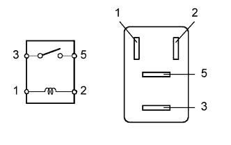
Remove the IG2 relay from the engine room No. 1 relay block.
Check the resistance.
- Standard resistance:
Tester Connection
| Specified Condition
|
3 - 5
| 10 kΩ or higher
|
3 - 5
| Below 1 Ω
(When battery voltage applied to terminals 1 and 2)
|
Reinstall the relay.
| 8.CHECK WIRE HARNESS (ECM - ENGINE ROOM NO. 1 RELAY BLOCK) |
Disconnect the A12 ECM connector.
Remove the IG2 relay from the engine room No. 1 relay block.
Measure the resistance of the wire harness side connectors.
- Standard resistance:
Tester Connection
| Specified Condition
|
A12-25 (IGSW) - Relay block IG2 relay terminal 5
| Below 1 Ω
|
A12-25 (IGSW) or Relay block IG2 relay terminal 5 - Body ground
| 10 KΩ or higher
|
Reconnect the ECM connector.
Reinstall the IG2 relay.
- Result:
Result
| Proceed to
|
Out of normal range
| A
|
Within normal range (w/ Entry and Start System)
| B
|
Within normal range (w/o Entry and Start System)
| C
|
| |
|
| | CHECK WIRE HARNESS (IGNITION SWITCH - ENGINE ROOM NO. 1 RELAY BLOCK) |
|
|
| A |
|
|
|
| REPAIR OR REPLACE HARNESS AND CONNECTOR |
|
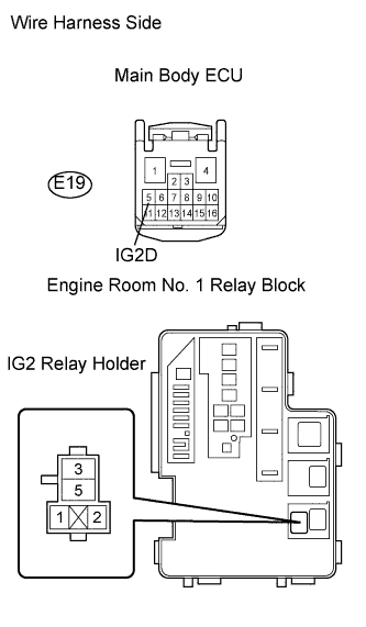
| 9.CHECK WIRE HARNESS (MAIN BODY ECU - ENGINE ROOM NO. 1 RELAY BLOCK) |
Remove the instrument panel junction block (main body ECU).
Remove the IG2 relay from the engine room No. 1 relay block.
Measure the resistance of the wire harness side connectors.
- Standard resistance:
Tester Connection
| Specified Condition
|
E19-5 (IG2D) - Relay block IG2 relay terminal 1
| Below 1 Ω
|
Relay block IG2 relay terminal 2 - Body ground
| Below 1 Ω
|
E19-5 (IG2D) - Body ground
| 10 kΩ or higher
|
Reconnect the main body ECU.
Reinstall the IG2 relay.
| | CHECK ENTRY AND START SYSTEM |
|
|
| OK |
|
|
|
| REPAIR OR REPLACE HARNESS AND CONNECTOR |
|
| 10.CHECK WIRE HARNESS (IGNITION SWITCH - ENGINE ROOM NO. 1 RELAY BLOCK) |
Disconnect the E5 ignition switch connector.
Remove the IG2 relay from the engine room No. 1 relay block.
Measure the resistance of the wire harness side connectors.
- Standard resistance:
Tester Connection
| Specified Condition
|
E5-6 (IG2) - Relay block IG2 relay terminal 1
| Below 1 Ω
|
Relay block IG2 relay terminal 2 - Body ground
| Below 1 Ω
|
E5-6 (IG2) - Body ground
| 10 kΩ or higher
|
Reconnect the ignition switch connector.
Reinstall the IG2 relay.
| | REPAIR OR REPLACE HARNESS AND CONNECTOR |
|
|
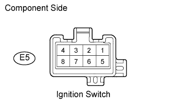
| 11.INSPECT IGNITION SWITCH ASSEMBLY |
Disconnect the E5 ignition switch connector.
Measure the resistance of the terminals shown below.
- Standard resistance:
Condition
| Tester Condition
| Specified Condition
|
OFF
| Between all terminals
| 1 MΩ or more
|
ACC
| 2 - 3
| 1 Ω or less
|
ON
| 2 - 4, 6 - 7
| 1 Ω or less
|
START
| 1 - 2, 2 - 4, 6 - 7, 7 - 8
| 1 Ω or less
|
Reconnect the ignition switch connector.
| | REPAIR OR REPLACE HARNESS AND CONNECTOR |
|
|
| OK |
|
|
|
| REPLACE IGNITION SWITCH ASSEMBLY |
|