Корпус Дроссельной Заслонки Дизельного Двигателя - Узлы И Детали
Land Cruiser Prado GRJ150 TRJ150 TRJ155 KDJ150 TRJ155 LJ150 - СИСТЕМА УПРАВЛЕНИЯ ДВИГАТЕЛЕМ 5L-E
КОРПУС ДРОССЕЛЬНОЙ ЗАСЛОНКИ ДИЗЕЛЬНОГО ДВИГАТЕЛЯ - УЗЛЫ И ДЕТАЛИ

1 / 1
Terminals TC and CG are located in the DLC3.
The DLC3 is located under the instrument panel under cover. When terminals TC and CG are connected, DTCs in normal mode or test mode can be read from the Malfunction Indicator Lamp (MIL) in the combination meter assembly.
Also, terminal SIL is located in the DLC3. This terminal is used for M-OBD communication with the intelligent tester.

| 1.CHECK DLC3 (CHECK VOLTAGE) |

Measure the voltage according to the value(s) in the table below.
| Tester Connection | Condition | Specified Condition |
| G48-16 (BAT) - G48-4 (CG) | Always | 11 to 14 V |
| *a | Front view of wire harness connector (to DLC3) |
|
| ||||
| OK | |
| 2.CHECK HARNESS AND CONNECTOR (ECM - DLC3) |
Disconnect the ECM connector.
Measure the resistance according to the value(s) in the table below.
| Tester Connection | Condition | Specified Condition |
| G61-15 (SIL) - G48-7 (SIL) | Always | Below 1 Ω |
| G61-4 (TC) - G48-13 (TC) | Always | Below 1 Ω |
| Tester Connection | Condition | Specified Condition |
| G61-15 (SIL) or G48-7 (SIL) - Body ground | Always | 10 kΩ or higher |
| G61-4 (TC) or G48-13 (TC) - Body ground | Always | 10 kΩ or higher |
Reconnect the ECM connector.
|
| ||||
| OK | ||
| ||
| 3.CHECK DLC3 |

Measure the resistance according to the value(s) in the table below.
| Tester Connection | Condition | Specified Condition |
| G48-4 (CG) - Body ground | Always | Below 1 Ω |
| *a | Front view of wire harness connector (to DLC3) |
|
| ||||
| OK | ||
| ||
The MIL is used to inform the user when the ECM has detected a vehicle malfunction.
By turning the ignition switch to ON, power is supplied to the MIL circuit and the ECM provides the circuit ground that illuminates the MIL.
Operation of the MIL should be checked visually: When the ignition switch is first turned to ON, the MIL should illuminate. When the engine is started, the MIL should turn off.

| 1.CHECK MIL CONDITION |
Check the MIL condition.
| Condition | Proceed to |
| MIL remains on | A |
| MIL does not illuminate | B |
|
| ||||
| A | |
| 2.CHECK IF MIL TURNS OFF |
Connect the intelligent tester to the DLC3.
Turn the ignition switch to ON and turn the tester on.
Check if DTCs have been stored (See page ). If DTCs are stored, write them down.
Clear the DTCs using the intelligent tester (See page ).
Check that the MIL turns off.
|
| ||||
| OK | ||
| ||
| 3.CHECK HARNESS AND CONNECTOR (FOR SHORT) |
Disconnect the ECM connector.
Turn the ignition switch to ON.
Check that the MIL is not illuminated.
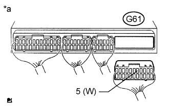
| *a | Rear view of wire harness connector (to ECM) |
Reconnect the ECM connector.
|
| ||||
| OK | ||
| ||
| 4.CHECK HARNESS AND CONNECTOR (ECM - COMBINATION METER ASSEMBLY) |
Disconnect the ECM connector.
Disconnect the combination meter assembly connector.
Measure the resistance according to the value(s) in the table below.
| Tester Connection | Condition | Specified Condition |
| G61-5 (W) - G7-7 (CHK) | Always | Below 1 Ω |
| Tester Connection | Condition | Specified Condition |
| G61-5 (W) or G7-7 (CHK) - Body ground | Always | 10 kΩ or higher |
Reconnect the ECM connector.
Reconnect the combination meter assembly connector.
|
| ||||
| OK | ||
| ||
| 5.CHECK IF MIL ILLUMINATES |
Check that the MIL illuminates when turning the ignition switch to ON.
|
| ||||
| OK | ||
| ||
| 6.INSPECT COMBINATION METER ASSEMBLY (MIL CIRCUIT) |
Refer to the combination meter assembly troubleshooting procedures (See page ).
|
| ||||
| OK | ||
| ||
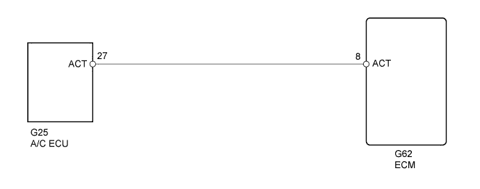
This circuit cuts air conditioning operation during vehicle acceleration in order to increase acceleration performance. During acceleration with the vehicle speed at 30 km/h (19 mph) or less and the accelerator pedal opening angle at 45° or more, the A/C magnetic switch is turned off for several seconds.
The air conditioning is also controlled using the engine coolant temperature output from the ECM to the A/C amplifier.
| 1.READ VALUE USING INTELLIGENT TESTER (CHECK OPERATION OF AIR CONDITIONING CUT CONTROL) |
Connect the intelligent tester to the DLC3.
Start the engine and turn the air conditioning switch on.
Enter the following menus: Powertrain / Engine and ECT / Active Test / A/C Cut SIG.
Check operation of the A/C magnetic clutch cut when air conditioning cut control is operated by the intelligent tester.
|
| ||||
| OK | ||
| ||
| 2.INSPECT ECM (ACT VOLTAGE) |
Start the engine.
Measure the voltage according to the value(s) in the table below.
| Tester Connection | Condition | Specified Condition |
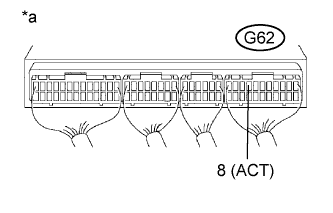
| G62-8 (ACT) - Body ground | Engine idling | 11 to 14 V |
| G62-8 (ACT) - Body ground | Ignition switch ON, engine stopped | 0 to 3 V |
| *a | Component with harness connected (ECM) |
|
| ||||
| OK | ||
| ||
| 3.CHECK HARNESS AND CONNECTOR (ECM - AIR CONDITIONING AMPLIFIER) |
Disconnect the A/C amplifier connector.
Disconnect the ECM connector.
Measure the resistance according to the value(s) in the table below.
| Tester Connection | Condition | Specified Condition |
| G25-27 (ACT) - G62-8 (ACT) | Always | Below 1 Ω |
| Tester Connection | Condition | Specified Condition |
| G25-27 (ACT) or G62-8 (ACT) - Body ground | Always | 10 kΩ or higher |
Reconnect the A/C amplifier connector.
Reconnect the ECM connector.
|
| ||||
| OK | ||
| ||
| 1.CHECK ECM (ACT VOLTAGE) |
Start the engine.
Measure the voltage according to the value(s) in the table below.
| Tester Connection | Condition | Specified Condition |
| G62-8 (ACT) - Body ground | Engine idling | 11 to 14 V |
| G62-8 (ACT) - Body ground | Ignition switch ON, engine stopped | 0 to 3 V |
| *a | Component with harness connected (ECM) |
|
| ||||
| OK | ||
| ||
| 2.CHECK HARNESS AND CONNECTOR (ECM - AIR CONDITIONING AMPLIFIER) |
Disconnect the A/C amplifier connector.
Disconnect the ECM connector.
Measure the resistance according to the value(s) in the table below.
| Tester Connection | Condition | Specified Condition |
| G25-27 (ACT) - G62-8 (ACT) | Always | Below 1 Ω |
| Tester Connection | Condition | Specified Condition |
| G25-27 (ACT) or G62-8 (ACT) - Body ground | Always | 10 kΩ or higher |
Reconnect the A/C amplifier connector.
Reconnect the ECM connector.
|
| ||||
| OK | ||
| ||
When the A/C compressor is on, the A/C amplifier sends the A/C signal to the ECM and the ECM increases the fuel injection volume to improve driveability during engine idling.

| 1.READ VALUE USING INTELLIGENT TESTER (AIR CONDITIONING SIGNAL) |
Connect the intelligent tester to the DLC3.
Start the engine.
Turn the A/C switch on.
Enter the following menus: Powertrain / Engine and ECT / Data List / A/C SIG.
| Switch Condition | A/C SIG |
| A/C switch off | OFF |
| A/C switch on | ON |
|
| ||||
| OK | ||
| ||
| 2.CHECK ECM (AC1 VOLTAGE) |
Start the engine.
Measure the voltage according to the value(s) in the table below.
| Tester Connection | Switch Condition | Specified Condition |
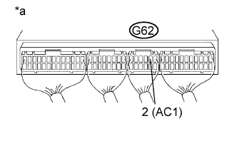
| G62-2 (AC1) - Body ground | A/C switch on | Below 1.5 V |
| G62-2 (AC1) - Body ground | A/C switch off | 7.5 to 14 V |
| *a | Component with harness connected (ECM) |
|
| ||||
| OK | ||
| ||
| 3.CHECK HARNESS AND CONNECTOR (ECM - AIR CONDITIONING AMPLIFIER) |
Disconnect the A/C amplifier connector.
Disconnect the ECM connector.
Measure the resistance according to the value(s) in the table below.
| Tester Connection | Condition | Specified Condition |
| G25-17 (AC1) - G62-2 (AC1) | Always | Below 1 Ω |
| Tester Connection | Condition | Specified Condition |
| G25-17 (AC1) or G62-2 (AC1) - Body ground | Always | 10 kΩ or higher |
Reconnect the A/C amplifier connector.
Reconnect the ECM connector.
|
| ||||
| OK | ||
| ||
| 1.CHECK ECM (AC1 VOLTAGE) |
Start the engine.
Measure the voltage according to the value(s) in the table below.
| Tester Connection | Switch Condition | Specified Condition |
| G62-2 (AC1) - Body ground | A/C switch on | Below 1.5 V |
| G62-2 (AC1) - Body ground | A/C switch off | 7.5 to 14 V |
| *a | Component with harness connected (ECM) |
|
| ||||
| OK | ||
| ||
| 2.CHECK HARNESS AND CONNECTOR (ECM - AIR CONDITIONING AMPLIFIER) |
Disconnect the A/C amplifier connector.
Disconnect the ECM connector.
Measure the resistance according to the value(s) in the table below.
| Tester Connection | Condition | Specified Condition |
| G25-17 (AC1) - G62-2 (AC1) | Always | Below 1 Ω |
| Tester Connection | Condition | Specified Condition |
| G25-17 (AC1) or G62-2 (AC1) - Body ground | Always | 10 kΩ or higher |
Reconnect the A/C amplifier connector.
Reconnect the ECM connector.
|
| ||||
| OK | ||
| ||
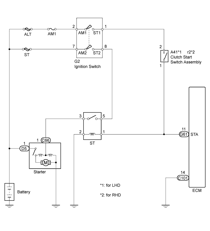
When the engine is cranked, the intake air flow becomes slow so fuel vaporization is poor. A rich mixture is therefore necessary in order to achieve good startability. While the engine is being cranked, the battery voltage is applied to terminal STA of the ECM. The starter signal is mainly used to increase the fuel injection volume for starting and after-start injection control.
| 1.READ VALUE USING INTELLIGENT TESTER (STA SIGNAL) |
Connect the intelligent tester to the DLC3.
Turn the ignition switch to ON and turn the tester on.
Enter the following menus: Powertrain / Engine and ECT / Data List / Starter Signal.
Read the STA signal on the intelligent tester while the starter operates.
| Ignition Switch Position | STA Signal |
| LOCK, ACC, ON | OFF |
| START | ON |
|
| ||||
| OK | ||
| ||
| 2.CHECK HARNESS AND CONNECTOR (CLUTCH START SWITCH - ECM) |
Disconnect the clutch start switch connector.
Disconnect the ECM connector.
Measure the resistance according to the value(s) in the table below.
| Tester Connection | Condition | Specified Condition |
| A41-1 - G61-11 (STA) | Always | Below 1 Ω |
| Tester Connection | Condition | Specified Condition |
| r2-1 - G61-11 (STA) | Always | Below 1 Ω |
| Tester Connection | Condition | Specified Condition |
| A41-1 or G61-11 (STA) - Body ground | Always | 10 kΩ higher |
| Tester Connection | Condition | Specified Condition |
| r2-1 or G61-11 (STA) - Body ground | Always | 10 kΩ higher |
Reconnect the clutch start switch connector.
Reconnect the ECM connector.
|
| ||||
| OK | ||
| ||
| 1.CHECK ECM (STA VOLTAGE) |
Turn the ignition switch to ON.
Measure the voltage according to the value(s) in the table below.
| Tester Connection | Condition | Specified Condition |
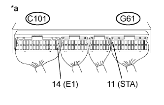
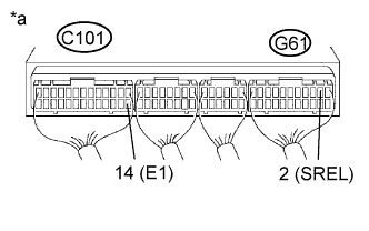
| G61-11 (STA) - C101-14 (E1) | Cranking | 6 V or higher |
| *a | Component with harness connected (ECM) |
|
| ||||
| OK | ||
| ||
| 2.CHECK HARNESS AND CONNECTOR (CLUTCH START SWITCH - ECM) |
Disconnect the clutch start switch connector.
Disconnect the ECM connector.
Measure the resistance according to the value(s) in the table below.
| Tester Connection | Condition | Specified Condition |
| A41-1 - G61-11 (STA) | Always | Below 1 Ω |
| Tester Connection | Condition | Specified Condition |
| r2-1 - G61-11 (STA) | Always | Below 1 Ω |
| Tester Connection | Condition | Specified Condition |
| A41-1 or G61-11 (STA) - Body ground | Always | 10 kΩ higher |
| Tester Connection | Condition | Specified Condition |
| r2-1 or G61-11 (STA) - Body ground | Always | 10 kΩ higher |
Reconnect the clutch start switch connector.
Reconnect the ECM connector.
|
| ||||
| OK | ||
| ||
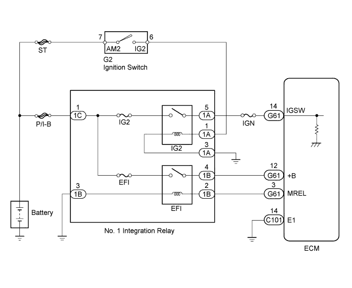
When the ignition switch is turned to ON, the battery voltage is applied to terminal IGSW of the ECM. The ECM "MREL" output signal causes current to flow to the EFI relay coil, closing the contacts of the EFI relay and supplying power to terminal +B of the ECM.
| 1.CHECK ECM (+B VOLTAGE) |

Turn the ignition switch to ON.
Measure the voltage according to the value(s) in the table below.
| Tester Connection | Switch Condition | Specified Condition |
| G61-12 (+B) - C101-14 (E1) | Ignition switch ON | 11 to 14 V |
| *a | Component with harness connected (ECM) |
|
| ||||
| OK | ||
| ||
| 2.CHECK HARNESS AND CONNECTOR (ECM - BODY GROUND) |
Disconnect the ECM connector.
Measure the resistance according to the value(s) in the table below.
| Tester Connection | Condition | Specified Condition |
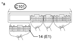
| C101-14 (E1) - Body ground | Always | Below 1 Ω |
| *a | Rear view of wire harness connector (to ECM) |
Reconnect the ECM connector.
|
| ||||
| OK | |
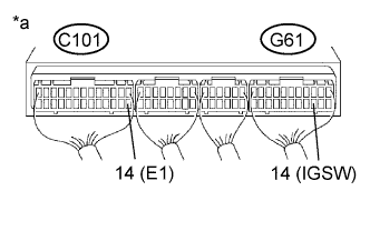
| 3.CHECK ECM (IGSW VOLTAGE) |
Turn the ignition switch to ON.
Measure the voltage according to the value(s) in the table below.
| Tester Connection | Switch Condition | Specified Condition |
| G61-14 (IGSW) - C101-14 (E1) | Ignition switch ON | 11 to 14 V |
| *a | Component with harness connected (ECM) |
|
| ||||
| OK | |
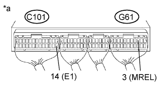
| 4.CHECK ECM (MREL VOLTAGE) |
Turn the ignition switch to ON.
Measure the voltage according to the value(s) in the table below.
| Tester Connection | Switch Condition | Specified Condition |
| G61-3 (MREL) - C101-14 (E1) | Ignition switch ON | 11 to 14 V |
| *a | Component with harness connected (ECM) |
|
| ||||
| OK | |
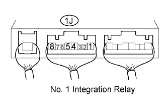
| 5.CHECK NO. 1 INTEGRATION RELAY (EFI) |
Turn the ignition switch to ON.
Measure the voltage according to the value(s) in the table below.
| Tester Connection | Condition | Specified Condition |
| 1B-4 - Body ground | Ignition switch ON | 10 to 14 V |
| *a | Rear view of wire harness connector (to No. 1 Integration Relay) |
Reconnect the No. 1 integration relay (EFI) connector.
|
| ||||
| OK | |
| 6.CHECK HARNESS AND CONNECTOR (NO. 1 INTEGRATION RELAY (EFI) - ECM AND BODY GROUND) |
Disconnect the No. 1 integration relay (EFI) connector from the engine room junction block.
Disconnect the ECM connector.
Measure the resistance according to the value(s) in the table below.
| Tester Connection | Condition | Specified Condition |
| 1B-2 - G61-3 (MREL) | Always | Below 1 Ω |
| 1B-4 - G61-12 (+B) | Always | Below 1 Ω |
| 1B-3 - Body ground | Always | Below 1 Ω |
| Tester Connection | Condition | Specified Condition |
| 1B-2 or G61-3 (MREL) - Body ground | Always | 10 kΩ or higher |
| 1B-4 or G61-12 (+B) - Body ground | Always | 10 kΩ or higher |
Reconnect the No. 1 integration relay (EFI) connector.
Reconnect the ECM connector.
|
| ||||
| OK | ||
| ||
| 7.INSPECT IGNITION SWITCH ASSEMBLY |
Inspect the ignition switch assembly (See page ).
|
| ||||
| OK | ||
| ||
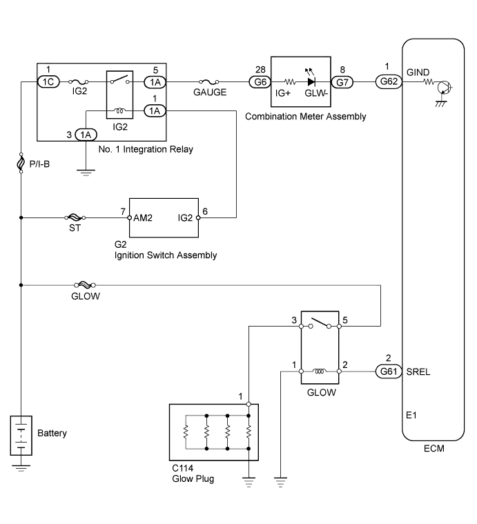
When the ignition switch is turned to ON, the ECM calculates the glow indicator lighting time/heating corresponding to the coolant temperature at that time and turns on the glow indicator light/glow plug relay (GLOW).
As ceramic is used for glow plug assembly material, current control is not performed.

| 1.CHECK GLOW INDICATOR LIGHT |
Turn the ignition switch to ON.
Check that the glow indicator light comes on.
|
| ||||
| OK | |
| 2.CHECK GLOW PLUG ASSEMBLY (INSTALLATION) |
Check that the glow plug assembly and glow plug wire are securely installed.
|
| ||||
| OK | |
| 3.INSPECT GLOW PLUG ASSEMBLY (RESISTANCE) |
Inspect the glow plug assembly (See page ).
|
| ||||
| OK | |
| 4.CHECK INDICATOR LIGHTING TIME AND AFTER GLOW TIME |
|
| ||||
| OK | |
| 5.READ OUTPUT DTC |
Connect the intelligent tester to the DLC3.
Turn the ignition switch to ON and turn the tester on.
Enter the following menus: Powertrain / Engine and ECT / DTC.
Read the DTCs (See page ).
| Result | Proceed to |
| DTC is not output | A |
| DTC is output | B |
|
| ||||
| A | |
| 6.INSPECT GLOW RELAY ASSEMBLY |
Inspect the glow plug relay (GLOW) (See page ).
|
| ||||
| OK | |
| 7.CHECK ECM (SREL VOLTAGE) |
Turn the ignition switch to the start position.
Measure the voltage according to the value(s) in the table below.
| Tester Connection | Condition | Specified Condition |
| G61-2 (SREL) - C101-14 (E1) | Cranking | 11 to 14 V |
| *a | Component with harness connected (ECM) |
|
| ||||
| OK | |
| 8.CHECK HARNESS AND CONNECTOR (GLOW RELAY - ECM AND BODY GROUND) |
Disconnect the ECM connector.
Remove the glow relay from the engine room relay block.
Measure the resistance according to the value(s) in the table below.
| Tester Connection | Condition | Specified Condition |
| G61-2 (SREL) - Relay block glow relay terminal 2 | Always | Below 1 Ω |
| Relay block glow relay terminal 1 - Body ground | Always | Below 1 Ω |
| Tester Connection | Condition | Specified Condition |
| G61-2 (SREL) or relay block glow relay terminal 2 - Body ground | Always | 10 kΩ or higher |
Reconnect the ECM connector.
Reinstall the glow relay.
|
| ||||
| OK | |
| 9.CHECK HARNESS AND CONNECTOR (GLOW PLUG RELAY (GLOW) - GLOW PLUG ASSEMBLY AND BATTERY) |
Disconnect the cable from the negative (-) battery terminal.
Disconnect the cable from the positive (+) battery terminal.
Remove the glow relay from the engine room relay block.
Disconnect the glow plug wire.
Measure the resistance according to the value(s) in the table below.
| Tester Connection | Condition | Specified Condition |
| Relay block glow relay terminal 3 - C114-1 | Always | Below 1 Ω |
| Relay block glow relay terminal 5 - Positive (+) battery terminal | Always | Below 1 Ω |
Reinstall the glow relay.
Reconnect the glow plug wire.
Reconnect the cable to the positive (+) battery terminal.
Reconnect the cable to the negative (-) battery terminal.
|
| ||||
| OK | ||
| ||
| 10.CHECK ECM (GIND VOLTAGE) |

Disconnect the ECM connector.
Turn the ignition switch to ON.
Measure the voltage according to the value(s) in the table below.
| Tester Connection | Switch Condition | Specified Condition |
| G62-1 (GIND) - C101-14 (E1) | Ignition switch ON | 11 to 14 V |
| *a | Rear view of wire harness connector (to ECM) |
Reconnect the ECM connector.
|
| ||||
| OK | ||
| ||
| 11.CHECK HARNESS AND CONNECTOR (ECM - COMBINATION METER ASSEMBLY) |
Disconnect the combination meter assembly connector.
Disconnect the ECM connector.
Measure the resistance according to the value(s) in the table below.
| Tester Connection | Condition | Specified Condition |
| G7-8 - G62-1 (GIND) | Always | Below 1 Ω |
Reconnect the combination meter assembly connector.
Reconnect the ECM connector.
|
| ||||
| OK | |
| 12.CHECK HARNESS AND CONNECTOR (COMBINATION METER ASSEMBLY - BATTERY) |

Disconnect the combination meter assembly connector.
Turn the ignition switch to ON.
Measure the voltage according to the value(s) in the table below.
| Tester Connection | Switch Condition | Specified Condition |
| G6-28 - Body ground | Ignition switch ON | 11 to 14 V |
| *a | Front view of wire harness connector (to Combination Meter Assembly) |
Reconnect the combination meter assembly connector.
|
| ||||
| OK | ||
| ||
Refer to DTC 19 (1) (See page ).
| DTC No. | DTC Detection Condition | Trouble Area |
| 19 (2) | Either of the ECM sensors has completed learning, and the voltage difference of the No. 1 and No. 2 sensors is more than 1.2 V or less than 0.4 V. | Open or short in accelerator pedal position sensor circuit Accelerator pedal position sensor ECM |
| One of the following continues for more than 2.0 seconds. The voltage difference of the No. 1 and No. 2 sensors is not within the specified range. VPA2 is 4.9 V or higher. Accelerator idling specified voltages of No. 1 and No. 2 are below 0.04 V. |
| Trouble Area | Accelerator pedal position expressed as voltage | |||
| Accelerator pedal released | Accelerator pedal depressed | |||
| ACCEL POS #1 | ACCEL POS #2 | ACCEL POS #1 | ACCEL POS #2 | |
| VC circuit open | 0 to 0.2 V | 0 to 0.2 V | 0 to 0.2 V | 0 to 0.2 V |
| VPA circuit open or shorted to ground | 0 to 0.2 V | 1.2 to 2.0 V | 0 to 0.2 V | 3.4 to 5.3 V |
| VPA2 circuit open or shorted to ground | 0.5 to 1.1 V | 0 to 0.2 V | 2.6 to 4.5 V | 0 to 0.2 V |
| E2 circuit open | 4.5 to 5.5 V | 4.5 to 5.5 V | 4.5 to 5.5 V | 4.5 to 5.5 V |
Refer to DTC 19 (1) (See page ).
| 1.READ VALUE USING INTELLIGENT TESTER (ACCELERATOR POSITION) |
Connect the intelligent tester to the DLC3.
Turn the ignition switch to ON.
Enter the following menus: Powertrain / Engine and ECT / Data List / Accel Position.
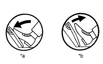
Check that the value displayed on the intelligent tester changes when repeatedly depressing and releasing the accelerator pedal.
| *a | Depressed |
| *b | Released |
|
| ||||
| OK | ||
| ||
| 2.CHECK HARNESS AND CONNECTOR (ECM - ACCELERATOR PEDAL POSITION SENSOR) |
Disconnect the accelerator pedal position sensor connector.
Disconnect the ECM connector.
Measure the resistance according to the value(s) in the table below.
| Tester Connection | Condition | Specified Condition |
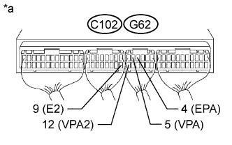
| A19-1 (VCP2) - C102-1 (VC) | Always | Below 1 Ω |
| A19-2 (EPA2) - C102-9 (E2) | Always | Below 1 Ω |
| A19-3 (VPA2) - G62-12 (VPA2) | Always | Below 1 Ω |
| A19-4 (VCPA) - G62-6 (VCPA) | Always | Below 1 Ω |
| A19-5 (EPA) - G62-4 (EPA) | Always | Below 1 Ω |
| A19-6 (VPA) - G62-5 (VPA) | Always | Below 1 Ω |
| Tester Connection | Condition | Specified Condition |
| A19-1 (VCP2) or C102-1 (VC) - Body ground | Always | 10 kΩ or higher |
| A19-2 (EPA2) or C102-9 (E2) - Body ground | Always | 10 kΩ or higher |
| A19-3 (VPA2) or G62-12 (VPA2) - Body ground | Always | 10 kΩ or higher |
| A19-4 (VCPA) or G62-6 (VCPA) - Body ground | Always | 10 kΩ or higher |
| A19-5 (EPA) or G62-4 (EPA) - Body ground | Always | 10 kΩ or higher |
| A19-6 (VPA) or G62-5 (VPA) - Body ground | Always | 10 kΩ or higher |
Reconnect the accelerator pedal position sensor connector.
Reconnect the ECM connector.
|
| ||||
| OK | ||
| ||
| 1.CHECK ECM (VPA, VPA2 VOLTAGE) |
Turn the ignition switch to ON.
Measure the voltage according to the value(s) in the table below.
| Tester Connection | Switch Condition | Specified Condition |
| G62-5 (VPA) - G62-4 (EPA) | Ignition switch ON | 0.5 to 1.1 V |
| G62-12 (VPA2) - C102-9 (E2) | Ignition switch ON | 1.2 to 2.0 V |
| Tester Connection | Switch Condition | Specified Condition |
| G62-5 (VPA) - G62-4 (EPA) | Ignition switch ON | 2.6 to 4.5 V |
| G62-12 (VPA2) - C102-9 (E2) | Ignition switch ON | 3.4 to 5.3 V |
| *a | Component with harness connected (ECM) |
|
| ||||
| OK | ||
| ||
| 2.CHECK HARNESS AND CONNECTOR (ECM - ACCELERATOR PEDAL POSITION SENSOR) |
Disconnect the accelerator pedal position sensor connector.
Disconnect the ECM connector.
Measure the resistance according to the value(s) in the table below.
| Tester Connection | Condition | Specified Condition |
| A19-1 (VCP2) - C102-1 (VC) | Always | Below 1 Ω |
| A19-2 (EPA2) - C102-9 (E2) | Always | Below 1 Ω |
| A19-3 (VPA2) - G62-12 (VPA2) | Always | Below 1 Ω |
| A19-4 (VCPA) - G62-6 (VCPA) | Always | Below 1 Ω |
| A19-5 (EPA) - G62-4 (EPA) | Always | Below 1 Ω |
| A19-6 (VPA) - G62-5 (VPA) | Always | Below 1 Ω |
| Tester Connection | Condition | Specified Condition |
| A19-1 (VCP2) or C102-1 (VC) - Body ground | Always | 10 kΩ or higher |
| A19-2 (EPA2) or C102-9 (E2) - Body ground | Always | 10 kΩ or higher |
| A19-3 (VPA2) or G62-12 (VPA2) - Body ground | Always | 10 kΩ or higher |
| A19-4 (VCPA) or G62-6 (VCPA) - Body ground | Always | 10 kΩ or higher |
| A19-5 (EPA) or G62-4 (EPA) - Body ground | Always | 10 kΩ or higher |
| A19-6 (VPA) or G62-5 (VPA) - Body ground | Always | 10 kΩ or higher |
Reconnect the accelerator pedal position sensor connector.
Reconnect the ECM connector.
|
| ||||
| OK | ||
| ||
In this system, the signal of the stop light switch is used to judge whether the stop light system is abnormal or not.
The stop light switch has a duplex system (signals STP and ST1-) to recognize the abnormality when the signals of depressing and releasing the brake pedal are detected simultaneously.
| Signal | Brake Pedal Released | In Transition | Brake Pedal Depressed |
| STP | Off | On | On |
| ST1- | On | On | Off |
| DTC No. | DTC Detection Condition | Trouble Area |
| 51 | Conditions (a), (b) and (c) continue for 0.5 seconds or more(1 trip detection logic): (a) Ignition switch is ON. (b) Brake pedal is released. (c) STP signal is off when ST1- signal is off. | Open or short in stop light switch signal circuit Stop light switch ECM |

| 1.READ VALUE USING INTELLIGENT TESTER (STOP LIGHT SWITCH) |
Connect the intelligent tester to the DLC3.
Turn the ignition switch to ON.
Enter the following menus: Powertrain / Engine and ECT / Data List / Stop Light SW.
| Brake Pedal | Display |
| Depressed | Stop Light SW ON |
| Released | Stop Light SW OFF |
|
| ||||
| OK | ||
| ||
| 2.CHECK ECM (STP, ST1- VOLTAGE) |

Turn the ignition switch to ON.
Measure the voltage according to the value(s) in the table below.
| Tester Connection | Brake Pedal Condition | Specified Condition |
| G61-19 (STP) - C101-14 (E1) | Depressed | 11 to 14 V |
| Released | Below 1.5 V | |
| G62-11 (ST1-) - C101-14 (E1) | Depressed | Below 1.5 V |
| Released | 11 to 14 V |
| *a | Brake pedal depressed |
| *b | Brake pedal released |
| *c | Component with harness connected (ECM) |
|
| ||||
| OK | ||
| ||
| 3.INSPECT STOP LIGHT SWITCH |
Inspect the stop light switch (See page ).
|
| ||||
| OK | |
| 4.CHECK HARNESS AND CONNECTOR (ECM - STOP LIGHT SWITCH) |
Disconnect the stop light switch connector.
Disconnect the ECM connectors.
Measure the resistance according to the value(s) in the table below.
| Tester Connection | Condition | Specified Condition |
| A5-1 - G61-19 (STP) | Always | Below 1 Ω |
| A5-3 - G62-11 (ST1-) | Always | Below 1 Ω |
| Tester Connection | Condition | Specified Condition |
| A5-1 or G61-19 (STP) - Body ground | Always | 10 kΩ or higher |
| A5-3 or G62-11 (ST1-) - Body ground | Always | 10 kΩ or higher |
Reconnect the stop light switch connector.
Reconnect the ECM connector.
|
| ||||
| OK | ||
| ||
| 1.CHECK STOP LIGHT (OPERATION) |
Check if the stop lights go on and off normally when the brake pedal is depressed and released.
|
| ||||
| OK | |
| 2.CHECK ECM (STP, ST1- VOLTAGE) |
Turn the ignition switch to ON.
Measure the voltage according to the value(s) in the table below.
| Tester Connection | Brake Pedal Condition | Specified Condition |
| G61-19 (STP) - C101-14 (E1) | Depressed | 11 to 14 V |
| Released | Below 1.5 V | |
| G62-11 (ST1-) - C101-14 (E1) | Depressed | Below 1.5 V |
| Released | 11 to 14 V |
| *a | Brake pedal depressed |
| *b | Brake pedal released |
| *c | Component with harness connected (ECM) |
|
| ||||
| OK | ||
| ||
| 3.INSPECT STOP LIGHT SWITCH |
Inspect the stop light switch (See page ).
|
| ||||
| OK | |
| 4.CHECK HARNESS AND CONNECTOR (ECM - STOP LIGHT SWITCH) |
Disconnect the stop light switch connector.
Disconnect the ECM connectors.
Measure the resistance according to the value(s) in the table below.
| Tester Connection | Condition | Specified Condition |
| A5-1 - G61-19 (STP) | Always | Below 1 Ω |
| A5-3 - G62-11 (ST1-) | Always | Below 1 Ω |
| Tester Connection | Condition | Specified Condition |
| A5-1 or G61-19 (STP) - Body ground | Always | 10 kΩ or higher |
| A5-3 or G62-11 (ST1-) - Body ground | Always | 10 kΩ or higher |
Reconnect the stop light switch connector.
Reconnect the ECM connector.
|
| ||||
| OK | ||
| ||