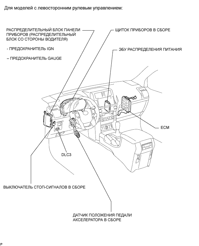
Система Sfi - Схема Системы
Land Cruiser Prado GRJ150 TRJ150 TRJ155 KDJ150 TRJ155 LJ150 - СИСТЕМА УПРАВЛЕНИЯ ДВИГАТЕЛЕМ 2TR-FE
СИСТЕМА SFI - СХЕМА СИСТЕМЫ


| 1.ИНИЦИАЛИЗАЦИЯ |
| 1. INSPECT STARTER RELAY (ST) |

Measure the resistance according to the value(s) in the table below.
| Tester Connection | Condition | Specified Condition |
| 3 - 5 | Battery voltage not applied to terminals 1 and 2 | 10 kΩ or higher |
| Battery voltage applied to terminals 1 and 2 | Below 1 Ω |
If the result is not as specified, replace the relay.
| 2. INSPECT GLOW PLUG RELAY (GLOW) |
Measure the resistance according to the value(s) in the table below.
| Tester Connection | Condition | Specified Condition |
| 3 - 5 | Battery voltage not applied to terminals 1 and 2 | 10 kΩ or higher |
| Battery voltage applied to terminals 1 and 2 | Below 1 Ω |
If the result is not as specified, replace the relay.
| 3. INSPECT FUEL PUMP RELAY (FUEL PMP) |

Measure the resistance according to the value(s) in the table below.
| Tester Connection | Condition | Specified Condition |
| 3 - 5 | Battery voltage not applied to terminals 1 and 2 | 10 kΩ or higher |
| Battery voltage applied to terminals 1 and 2 | Below 1 Ω |
If the result is not as specified, replace the relay.
| 4. INSPECT NO. 1 INTEGRATION RELAY (IG2) |
Check the IG2 fuse.
Measure the resistance according to the value(s) in the table below.
| Tester Connection | Condition | Specified Condition |
| IG2 fuse | Always | Below 1 Ω |
If the result is not as specified, replace the IG2 fuse.
Check the IG2 relay.

Measure the resistance according to the value(s) in the table below.
| Tester Connection | Condition | Specified Condition |
| 1C-1 - 1H-4 | Battery voltage not applied to terminals 1H-1 and 1H-3 | 10 kΩ or higher |
| Battery voltage applied to terminals 1H-1 and 1H-3 | Below 1 Ω |
| *a | Component without harness connected (Integration Relay) |
If the result is not as specified, replace the integration relay.
| 5. INSPECT NO. 1 INTEGRATION RELAY (EFI) |
Check the EFI fuse.
Measure the resistance according to the value(s) in the table below.
| Tester Connection | Condition | Specified Condition |
| EFI fuse | Always | Below 1 Ω |
If the result is not as specified, replace the EFI fuse.
Check the EFI relay.
Measure the resistance according to the value(s) in the table below.
| Tester Connection | Condition | Specified Condition |
| 1C-1 - 1I-4 | Battery voltage not applied to terminals 1I-2 and 1I-3 | 10 kΩ or higher |
| Battery voltage applied to terminals 1I-2 and 1I-3 | Below 1 Ω |
| *a | Component without harness connected (Integration Relay) |
If the result is not as specified, replace the integration relay.
| 6. INSPECT MAIN BODY ECU (DRIVER SIDE JUNCTION BLOCK) |
Inspect the ACC relay.
Measure the resistance according to the value(s) in the table below.

| *a | Component without harness connected (Main Body ECU) | - | - |
| Tester Connection | Condition | Specified Condition |
| 2D-17 - 2K-1 | Battery voltage not applied to terminals 2A-48 and 2D-4 | 10 kΩ or higher |
| Battery voltage applied to terminals 2A-48 and 2D-4 | Below 1 Ω |
If the result is not as specified, replace the main body ECU.
Inspect the IG1 No. 1 relay.
Measure the resistance according to the value(s) in the table below.
| *a | Component without harness connected (Main Body ECU) | - | - |
| Tester Connection | Condition | Specified Condition |
| 2A-31 - 2K-1 | Battery voltage not applied to terminals 2A-52 and 2D-4 | 10 kΩ or higher |
| Battery voltage applied to terminals 2A-52 and 2D-4 | Below 1 Ω |
If the result is not as specified, replace the main body ECU.
| 1. INSTALL MANIFOLD ABSOLUTE PRESSURE SENSOR |
Install the manifold absolute pressure sensor with the 2 bolts.
Connect the vacuum hose and manifold absolute pressure sensor connector.
| 1. REMOVE MANIFOLD ABSOLUTE PRESSURE SENSOR |
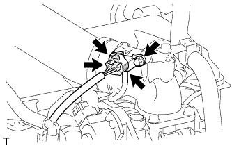
Disconnect the manifold absolute pressure sensor connector and vacuum hose.
Remove the 2 bolts and manifold absolute pressure sensor.
| 1. INSPECT MANIFOLD ABSOLUTE PRESSURE SENSOR |
Inspect the power source voltage.
Disconnect the manifold absolute pressure sensor connector.

Measure the voltage according to the value(s) in the table below.
| Tester Connection | Switch Condition | Specified Condition |
| C83-3 (VC) - C83-1 (E) | Ignition switch ON | 4.75 to 5.25 V |
| *a | Front view of wire harness connector (to Manifold Absolute Pressure Sensor) |
If the result is not as specified, inspect the wire harness or ECM (See page ).
Connect the manifold absolute pressure sensor connector.
Check the power supply.
Turn the ignition switch to ON.
Disconnect the vacuum hose from the manifold absolute pressure sensor.

Using SST, measure the voltage according to the value(s) in the table below.
| Tester Connection | Condition | Specified Condition |
| C102-2 (PIM) - C102-9 (E2) | 60 kPa (0.61 kgf/cm2, 8.7 psi) | 0.4 to 0.6 V |
| 87 kPa (0.89 kgf/cm2, 12.6 psi) | 1.1 to 1.3 V |
| *a | Component with harness connected (ECM) |
If the result is not as specified, replace the manifold absolute pressure sensor.

| 1. INSTALL INTAKE AIR TEMPERATURE SENSOR |
Install the intake air temperature sensor.
Attach the clamp and connect the intake air temperature sensor connector.
| 1. INSPECT INTAKE AIR TEMPERATURE SENSOR |

Measure the resistance according to the value(s) in the table below.
| Tester Connection | Condition | Specified Condition |
| 1 - 2 | 20°C | 2.09 to 2.69 kΩ |
| *1 | Resistance kΩ |
| *2 | Temperature °C (°F) |
| *3 | Acceptable |
| *a | Component without harness connected (Intake Air Temperature Sensor) |
If the result is not as specified, replace the intake air temperature sensor.