Распредвал - Узлы И Детали
Land Cruiser Prado GRJ150 TRJ150 TRJ155 KDJ150 TRJ155 LJ150 - МЕХАНИЧЕСКАЯ ЧАСТЬ ДВИГАТЕЛЯ 5L-E
РАСПРЕДВАЛ - УЗЛЫ И ДЕТАЛИ
1 / 5

2 / 5
3 / 5

4 / 5

5 / 5
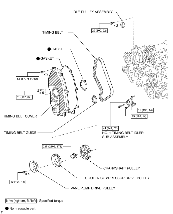
| 1. INSTALL NO. 1 TIMING BELT IDLER SUB-ASSEMBLY |

Install the No. 1 belt idler with the 3 bolts.

| Item | Length |
| A | 76.5 mm (3.01 in.) |
| B | 42.9 mm (1.69 in.) |
| C | 41.3 mm (1.63 in.) |
| 2. SET NO. 1 CYLINDER TO TDC/COMPRESSION |

Using the crankshaft pulley bolt, align the groove of the crankshaft pulley with the timing pointer by turning the crankshaft clockwise.
| *1 | Timing Mark |
 | Turn |

Set the timing and drive pulleys at each position.
| 3. INSTALL TIMING BELT |

Remove any oil or water on each pulley, and keep them clean.
Install the timing belt to the crankshaft timing and timing belt idlers.

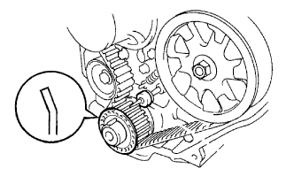
Using SST, slightly turn the injection pump drive pulley clockwise. Install the timing belt to the pulley, and align the timing marks of the drive pulley and timing belt case.
| *1 | Timing Mark |

Using SST, slightly turn the camshaft timing pulley clockwise. Install the timing belt to the timing pulley, and align the timing marks of the timing pulley and timing belt case.
| *1 | Timing Mark |
Check that the timing belt has tension between the injection pump drive and camshaft timing pulleys.
Install the timing belt to the No. 1 timing belt idler.

Loosen the No. 1 timing belt idler bolt (A), and stretch the timing belt.
Slowly turn the crankshaft pulley.
Tighten the No. 1 timing belt idler bolt.
| 4. CHECK NO. 1 CYLINDER TO TDC/COMPRESSION |
Slowly turn the crankshaft pulley 2 revolutions from TDC to TDC.
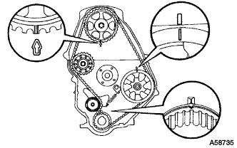
Check that the timing marks for each pulley align as shown in the illustration.
If the timing marks do not align, remove the timing belt and reinstall it.
| 5. INSTALL TIMING BELT GUIDE |
Install the timing belt guide with the cup side facing outward.
| 6. INSTALL TIMING BELT COVER |

Install 2 new gaskets to the timing belt cover.
| *1 | Gasket |
Install the timing belt cover with the 11 bolts and washers.
| 7. INSTALL IDLE PULLEY ASSEMBLY |
Install the idle pulley bracket with the 2 bolts.
| 8. INSTALL CRANKSHAFT PULLEY |
Align the key groove of the pulley with the pulley set key, and slide the pulley onto the crankshaft to install it.

Using SST, install the pulley bolt.
| *a | Turn |
| *b | Hold |
| 9. INSTALL VANE PUMP DRIVE PULLEY |
Install the vane pump drive pulley and cooler compressor drive pulley with the 4 bolts.
| 10. INSTALL FAN SHROUD |
Install the fan shroud (See page ).
| 11. CONNECT CABLE TO NEGATIVE BATTERY TERMINAL |
| 12. INSPECT ENGINE IDLE SPEED |
Warm up the engine.
When using the intelligent tester:
Connect the intelligent tester to the DLC3.

When not using an intelligent tester:
Using SST, connect the tachometer test probe to terminal 9 (TAC) of the DLC3.
Check the idle speed.
| *a | Front View of DLC3 |
| 13. INSPECT MAXIMUM ENGINE SPEED |
Start the engine.
Fully depress the accelerator pedal.
Check the maximum speed.
| 1. INSPECT TIMING BELT |

| *1 | Oil |
| *2 | Water |
If there is premature parting:
If the belt teeth are cracked or damaged, check if either camshaft is locked.
If there is noticeable wear or cracks on the belt face, check if there are nicks on the side of the idler pulley lock and water pump.
If there is wear or damage to only one side of the belt, check the belt guide and the alignment of each pulley.
If there is noticeable wear on the belt teeth:
If necessary, replace the timing belt.
| 2. INSPECT NO. 1 TIMING BELT IDLER SUB-ASSEMBLY |

Visually check the seal portion of the No. 1 timing belt idler for oil leakage.
| *1 | Seal |
 | Turn |
If leakage is found, replace the No. 1 timing belt idler sub-assembly.
Check that the No. 1 timing belt idler turns smoothly. If necessary, replace the No. 1 timing belt idler sub-assembly.
| 3. INSPECT IDLER TENSION SPRING |

Measure the free length of the tension spring.
| *1 | Free Length |
If the free length is not as specified, replace the idler tension spring.
Measure the tension of the tension spring at the installed length.
If the installed tension is not as specified, replace the idler tension spring.
| 1. DISCONNECT CABLE FROM NEGATIVE BATTERY TERMINAL |
| 2. REMOVE FAN SHROUD |
Remove the fan shroud (See page ).
| 3. REMOVE VANE PUMP DRIVE PULLEY |

Remove the 4 bolts, vane pump drive pulley and cooler compressor drive pulley.
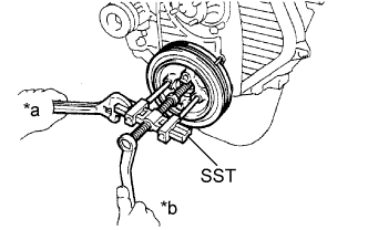
| 4. REMOVE CRANKSHAFT PULLEY |

Using SST, remove the pulley bolt.
| *a | Hold |
| *b | Turn |
Using SST, remove the pulley.
| *a | Hold |
| *b | Turn |
| 5. REMOVE IDLE PULLEY ASSEMBLY |

Remove the 2 bolts and Idle pulley bracket.
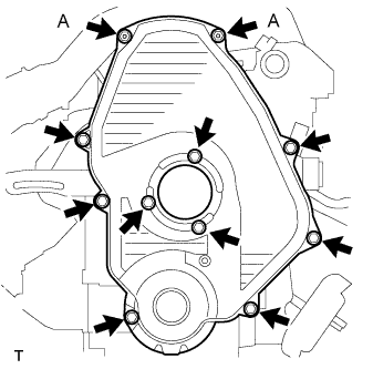
| 6. REMOVE TIMING BELT COVER |

Remove the 11 bolts, washers, timing belt cover, and 2 gaskets.
| 7. REMOVE TIMING BELT GUIDE |
Remove the timing belt guide.
| 8. SET NO. 1 CYLINDER TO TDC/COMPRESSION |
Using the crankshaft pulley bolt, align the groove of the crankshaft pulley with the timing pointer by turning the crankshaft clockwise.
| *1 | Timing Mark |
| Turn |

Check that the timing marks of the camshaft timing pulley and No. 2 timing belt cover are aligned.
| *1 | Timing Mark |
If not, turn the crankshaft 1 revolution (360°).
| 9. REMOVE TIMING BELT |
Turn the crankshaft 90° counterclockwise, and align the timing mark of the crankshaft timing pulley with the protrusion of the timing belt case.
| Turn |

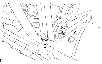
Loosen the No. 1 timing belt idler bolt (A), and shift the idler to the left as far as possible.
| Pry |
 | Move |
Tighten the No. 1 timing belt idler bolt (A), and then relieve the timing belt tension.
Remove the timing belt.
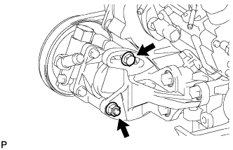
| 10. REMOVE NO. 1 TIMING BELT IDLER SUB-ASSEMBLY |
Remove the 2 bolts (A and B).

Loosen the bolt (C), and remove the No. 1 timing belt idler.
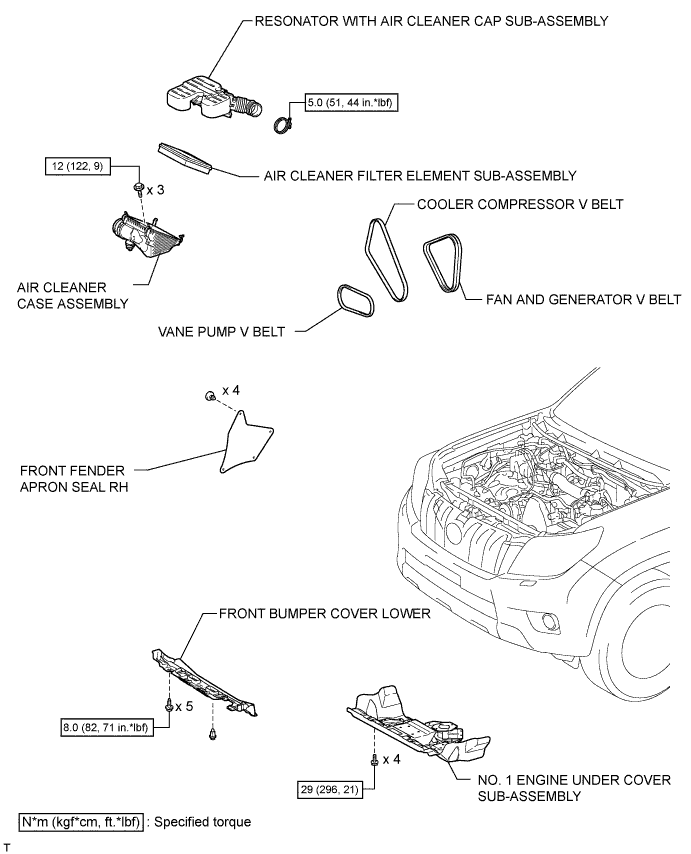
| 1. REMOVE RESONATOR WITH AIR CLEANER CAP SUB-ASSEMBLY |

Disconnect the sensor connector.
Detach the wire harness clamp.
Loosen the hose clamp and remove the resonator with air cleaner cap.

Detach the 4 hook clamps, and then remove the air cleaner cap and resonator with air cleaner cap.
| 2. REMOVE INTAKE AIR CONNECTOR SUB-ASSEMBLY |

Loosen the hose clamp and remove the 2 bolts and intake pipe.
| 3. REMOVE CYLINDER HEAD COVER SUB-ASSEMBLY |
Remove the 9 bolts, nut, cylinder head cover and gasket.
| 4. SET NO. 1 CYLINDER TO TDC/COMPRESSION |

Turn the crankshaft pulley and align its groove with the timing pointer.
Check that the valve lifters for the No. 1 cylinder are loose and the valve lifters for the No. 4 cylinder are tight.
If not, turn the crankshaft 1 revolution (360°) and align the mark as above.
| 5. INSPECT VALVE CLEARANCE |

Check only the valves indicated in the illustration.
Using a feeler gauge, measure the clearance between the valve lifter and camshaft.
| Item | Specified Condition |
| Intake | 0.20 to 0.30 mm (0.00787 to 0.0118 in.) |
| Exhaust | 0.40 to 0.50 mm (0.0158 to 0.0197 in.) |
| *1 | No. 1 EX |
| *2 | No. 3 EX |
| *3 | No. 1 IN |
| *4 | No. 2 IN |
Record the out-of-specification valve clearance measurements. They will be used later to determine the required replacement adjusting shim.
Turn the crankshaft 1 revolution (360°) and align the mark as above.

Check only the valves indicated in the illustration.
| *1 | No. 2 EX |
| *2 | No. 4 EX |
| *3 | No. 3 IN |
| *4 | No. 4 IN |
Using a feeler gauge, measure the clearance between the valve lifter and camshaft.
| Item | Specified Condition |
| Intake | 0.20 to 0.30 mm (0.00787 to 0.0118 in.) |
| Exhaust | 0.40 to 0.50 mm (0.0158 to 0.0197 in.) |
Record the out-of-specification valve clearance measurements. They will be used later to determine the required replacement adjusting shim.
| 6. ADJUST VALVE CLEARANCE |

Remove the adjusting shim.
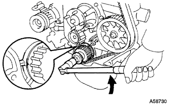
Turn the crankshaft so that the cam lobe of the camshaft on the valve being adjusted points upward.
Using SST, press down the valve lifter.
Position the notch of the valve lifter so that it faces the exhaust manifold side.

Remove the adjusting shim with a screwdriver and magnet hand.
Determine the replacement adjusting shim size according to the formula and charts below.
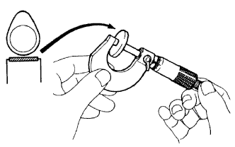
Using a micrometer, measure the thickness of the removed shim.
Calculate the thickness of a new shim so that the valve clearance comes within the specified value.
T = Thickness of removed shim
A = Measured valve clearance
N = Thickness of new shim
| Intake | N = T + (A - 0.25 mm (0.00984 in.)) |
| Exhaust | N = T + (A - 0.45 mm (0.0177 in.)) |
Select a new shim with a thickness as close as possible to the calculated value.

| *1 | Adjusting Shim Selection Chart (Intake) | *2 | Removed shim thickness mm (in.) |
| *3 | Measure clearance mm (in.) | - | - |
| Shim No. | Thickness | Shim No. | Thickness |
| 01 | 2.50 (0.0984) | 46 | 2.95 (0.116) |
| 42 | 2.55 (0.100) | 26 | 3.00 (0.118) |
| 06 | 2.60 (0.102) | 47 | 3.05 (0.120) |
| 43 | 2.65 (0.104) | 31 | 3.10 (0.122) |
| 11 | 2.70 (0.106) | 48 | 3.15 (0.124) |
| 44 | 2.75 (0.108) | 36 | 3.20 (0.126) |
| 16 | 2.80 (0.110) | 49 | 3.25 (0.128) |
| 45 | 2.85 (0.112) | 41 | 3.30 (0.130) |
| 21 | 2.90 (0.114) |
EXAMPLE:
A 2.80 mm (0.110 in.) shim is installed and the measured clearance is 0.350 mm (0.0138 in.). Replace the 2.80 mm (0.110 in.) shim with a No. 21 shim.

| *1 | Adjusting Shim Selection Chart (Exhaust) | *2 | Removed Shim Thickness mm (in.) |
| *3 | Measure Clearance mm (in.) | - | - |
| Shim No. | Thickness | Shim No. | Thickness |
| 01 | 2.50 (0.0984) | 46 | 2.95 (0.116) |
| 42 | 2.55 (0.100) | 26 | 3.00 (0.118) |
| 06 | 2.60 (0.102) | 47 | 3.05 (0.120) |
| 43 | 2.65 (0.104) | 31 | 3.10 (0.122) |
| 11 | 2.70 (0.106) | 48 | 3.15 (0.124) |
| 44 | 2.75 (0.108) | 36 | 3.20 (0.126) |
| 16 | 2.80 (0.110) | 49 | 3.25 (0.128) |
| 45 | 2.85 (0.112) | 41 | 3.30 (0.130) |
| 21 | 2.90 (0.114) |
EXAMPLE:
A 2.80 mm (0.110 in.) shim is installed and the measured clearance is 0.350 mm (0.0138 in.). Replace the 2.80 mm (0.110 in.) shim with a No. 11 shim.
Install a new adjusting shim.
Install a new adjusting shim to the valve lifter.
Remove SST.
Recheck valve clearance.
| 7. INSTALL CYLINDER HEAD COVER SUB-ASSEMBLY |
Remove any old packing (FIPG material).

Apply seal packing to the cylinder head as shown in the illustration.
| *1 | Seal Packing |
Install the gasket to the cylinder head cover.
Install the cylinder head cover with the 9 bolts and nut. Uniformly tighten the bolts and nut in several steps.
| 8. INSTALL INTAKE AIR CONNECTOR SUB-ASSEMBLY |
Install the intake pipe with the 2 bolts.
Tighten the intake pipe clamp.
| 9. INSTALL RESONATOR WITH AIR CLEANER CAP SUB-ASSEMBLY |
Вставьте петли крышки воздушного фильтра и шланг в корпус воздушного фильтра, а затем закрепите 4 откидных защелки.
Установите крышку воздушного фильтра и закрепите ее зажимом.
Закрепите зажим жгута проводов.
Подсоедините 2 зажима и разъем.
| 10. INSPECT ENGINE IDLE SPEED |
Warm up the engine.
When using the intelligent tester:
Connect the intelligent tester to the DLC3.
When not using an intelligent tester:
Using SST, connect the tachometer test probe to terminal 9 (TAC) of the DLC3.
Check the idle speed.
| *a | Front View of DLC3 |
| 11. INSPECT MAXIMUM ENGINE SPEED |
Start the engine.
Fully depress the accelerator pedal.
Check the maximum speed.
| 1. УСТАНОВИТЕ ПОЛИКЛИНОВОЙ РЕМЕНЬ ВЕНТИЛЯТОРА И ГЕНЕРАТОРА |
Установите поликлиновой ремень.

Отрегулируйте натяжение поликлинового ремня с помощью болта A.
Затяните болты B и C.
Проверьте натяжение поликлинового ремня .
| 2. УСТАНОВИТЕ ПОЛИКЛИНОВОЙ РЕМЕНЬ КОМПРЕССОРА СИСТЕМЫ КОНДИЦИОНИРОВАНИЯ |
Установите поликлиновой ремень.
Отрегулируйте натяжение поликлинового ремня с помощью болта B.
Затяните гайку А.
Проверьте натяжение поликлинового ремня .
| 3. УСТАНОВИТЕ ПОЛИКЛИНОВОЙ РЕМЕНЬ ЛОПАСТНОГО НАСОСА |
Установите поликлиновой ремень.
Отрегулируйте натяжение поликлинового ремня с помощью стержня.

Затяните болт А и гайку В.
Проверьте натяжение поликлинового ремня .
| 4. УСТАНОВИТЕ КОРПУС ВОЗДУШНОГО ФИЛЬТРА В СБОРЕ |
Install the air cleaner case with the 3 bolts.
| 5. УСТАНОВИТЕ ФИЛЬТРУЮЩИЙ ЭЛЕМЕНТ ВОЗДУШНОГО ФИЛЬТРА В СБОРЕ |
| 6. УСТАНОВИТЕ РЕЗОНАТОР С КРЫШКОЙ ВОЗДУШНОГО ФИЛЬТРА В СБОРЕ |
Вставьте петли крышки воздушного фильтра и шланг в корпус воздушного фильтра, а затем закрепите 4 откидных защелки.
Установите крышку воздушного фильтра и закрепите ее зажимом.
Закрепите зажим жгута проводов.
Подсоедините 2 зажима и разъем.
| 7. УСТАНОВИТЕ УПЛОТНЕНИЕ ФАРТУКА ПРАВОГО ПЕРЕДНЕГО КРЫЛА |
Install the front fender apron seal with the 4 clips.
| 8. УСТАНОВИТЕ ЗАЩИТУ КАРТЕРА ДВИГАТЕЛЯ № 1 В СБОРЕ |

Hook the engine under cover to the vehicle body as shown in the illustration.
Install the 4 bolts.
| 9. УСТАНОВИТЕ НИЖНЮЮ НАКЛАДКУ ПЕРЕДНЕГО БАМПЕРА |
Install the front bumper cover lower with the 5 bolts and clip.
| 1. REMOVE FRONT BUMPER COVER LOWER |
Remove the clip, 5 bolts and front bumper cover lower.
| 2. REMOVE NO. 1 ENGINE UNDER COVER SUB-ASSEMBLY |
Remove the 4 bolts.
Unhook the engine under cover from the vehicle body as shown in the illustration.
| 3. REMOVE FRONT FENDER APRON SEAL RH |
Remove the 4 clips and fender apron seal.
| 4. REMOVE RESONATOR WITH AIR CLEANER CAP SUB-ASSEMBLY |
Disconnect the sensor connector.
Detach the wire harness clamp.
Loosen the hose clamp and remove the resonator with air cleaner cap.
Detach the 4 hook clamps, and then remove the air cleaner cap and resonator with air cleaner cap.
| 5. REMOVE AIR CLEANER FILTER ELEMENT SUB-ASSEMBLY |
| 6. REMOVE AIR CLEANER CASE ASSEMBLY |

Remove the 3 bolts and air cleaner case.
| 7. REMOVE VANE PUMP V BELT |
Loosen bolt and nut, and remove the V belt.
| 8. REMOVE COOLER COMPRESSOR V BELT |

Loosen nut and adjusting bolt, and remove the V belt.
| *1 | Adjusting Bolt |
| 9. REMOVE FAN AND GENERATOR V BELT |

Loosen 2 bolts.
Loosen adjusting bolt, and remove the V belt.
| *1 | Adjusting Bolt |
| 1. INSPECT V BELT |

Visually check the belt for cracks, oiliness or wear. Check that the belt does not touch the bottom of the pulley groove.
| *a | CORRECT |
| *b | INCORRECT |
| *c | Clearance |
If necessary, replace the belt.

Check the vane pump V belt deflection by pressing on the belt at the point indicated in the illustration with 98 N (10 kgf, 22 lbf) of force.
| Item | Specified Condition |
| New belt | 8 to 10 mm (0.314 to 0.393 in.) |
| Used belt | 10 to 15 mm (0.393 to 0.590 in.) |
| *1 | Vane Pump Pulley |
| *2 | Crankshaft Pulley |
| Measuring Point for Belt Tension |
Reference:
Using a belt tension gauge, check the cooler compressor V belt tension.
| Item | Specified Condition |
| New belt | 441 to 539 N (45 to 55 kgf, 99.1 to 121.2 lbf) |
| Used belt | 196 to 343 N (20 to 35 kgf, 44.1 to 77.1 lbf) |

Check the cooler compressor V belt deflection by pressing on the belt at the point indicated in the illustration with 98 N (10 kgf, 22 lbf) of force.
| Item | Specified Condition |
| New belt | 11 to 15 mm (0.433 to 0.590 in.) |
| Used belt | 15 to 20 mm (0.590 to 0.787 in.) |
| *1 | Cooler Compressor |
| *2 | Idle Pulley |
| *3 | Crankshaft Pulley |
| Measuring Point for Belt Tension |
Reference:
Using a belt tension gauge, check the cooler compressor V belt tension.
| Item | Specified Condition |
| New belt | 372 to 608 N (38 to 62 kgf, 83.6 to 136.7 lbf) |
| Used belt | 196 to 392 N (20 to 40 kgf, 44.1 to 88.1 lbf) |

Check the fan and generator V belt deflection by pressing on the belt at the point indicated in the illustration with 98 N (10 kgf, 22 lbf) of force.
| Item | Specified Condition |
| New belt | 7.0 to 10 mm (0.276 to 0.393 in.) |
| Used belt | 10 to 14 mm (0.393 to 0.551 in.) |
| *1 | Water Pump Pulley |
| *2 | Generator |
| *3 | Crankshaft Pulley |
| Measuring Point for Belt Tension |
Reference:
Using a belt tension gauge, check the fan and generator V belt tension.
| Item | Specified Condition |
| New belt | 441 to 539 N (45 to 55 kgf, 99.1 to 121.2 lbf) |
| Used belt | 196 to 343 N (20 to 35 kgf, 44.1 to 77.1 lbf) |