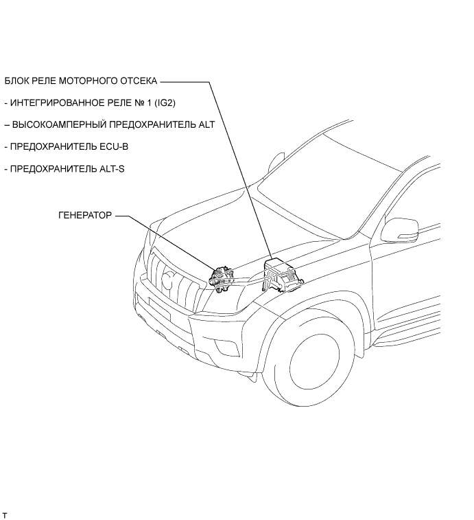
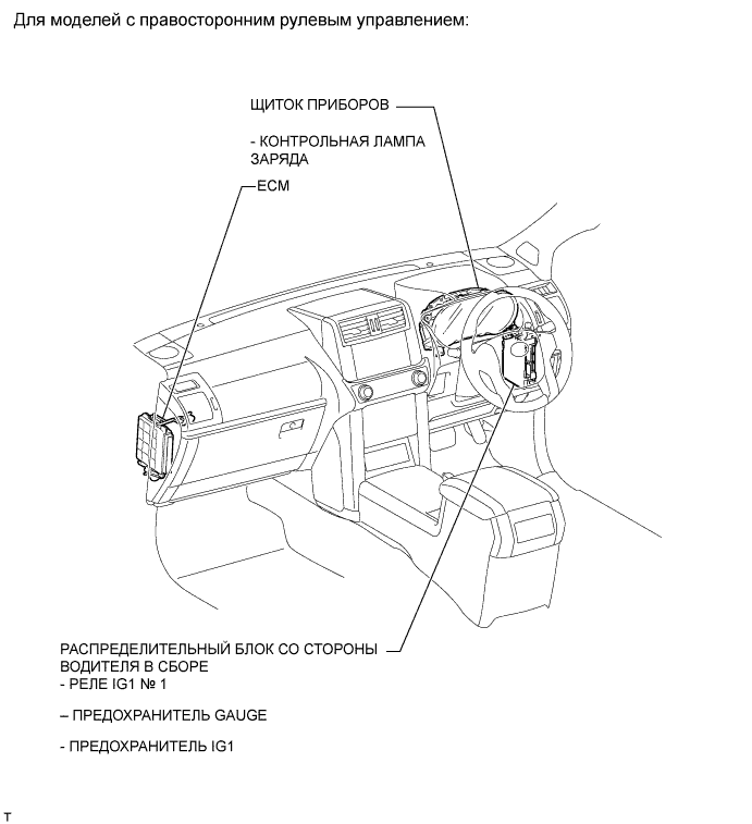
Система Зарядки Аккумуляторной Батареи - Схема Системы
Land Cruiser Prado GRJ150 TRJ150 TRJ155 KDJ150 TRJ155 LJ150 - АККУМУЛЯТОРНАЯ БАТАРЕЯ / СИСТЕМА ЗАРЯДКИ ДВИГАТЕЛЯ 2TR-FE
СИСТЕМА ЗАРЯДКИ АККУМУЛЯТОРНОЙ БАТАРЕИ - СХЕМА СИСТЕМЫ


| 1.Убедитесь, что провода аккумуляторной батареи подключены к соответствующим контактам. |
| 2.Отсоединяйте провода аккумуляторной батареи, когда выполняется быстрый заряд батареи. |
| 3.Не используйте для испытаний высоковольтный измеритель сопротивления изоляции. |
| 4.Никогда не отсоединяйте аккумуляторную батарею при работающем двигателе. |
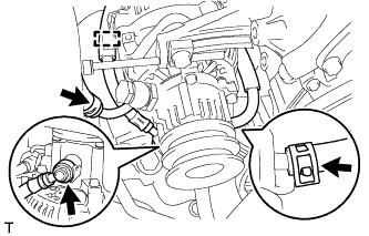
| 5.Убедитесь, что гайки кабеля для зарядки надежно затянуты на контакте B генератора и блоке реле моторного отсека. |
| 1. INSTALL GENERATOR ASSEMBLY |
Temporarily install the generator with the 2 bolts.
Connect the vacuum pump oil outlet hose.
Install 2 new gaskets and the vacuum pump oil inlet hose with the union bolt.
Connect the vacuum pump hose.
Attach the vacuum pump oil inlet hose to the cord clip.
Install the generator wire with the nut.
Install the terminal cap.
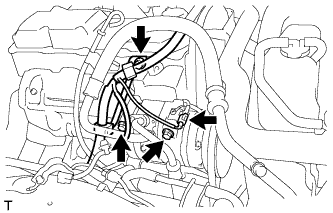
Connect the generator connector.
| 2. CONNECT COOLER COMPRESSOR ASSEMBLY |

Temporarily install the cooler compressor with the 2 bolts.
Temporarily install the idle pulley bracket with the 4 bolts.
Tighten the 6 bolts in the sequence shown in the illustration.
Connect the wire harness with the bolt.
Connect the cooler compressor connector.
| 3. INSTALL FAN AND GENERATOR V BELT |
Install the fan and generator V belt (See page ).
| 4. CONNECT CABLE TO NEGATIVE BATTERY TERMINAL |
| 1. INSTALL GENERATOR ROTOR ASSEMBLY |
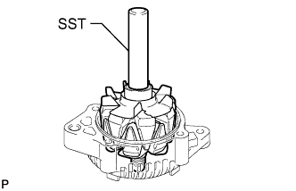
Using SST and a press, press in the generator rotor.
Place the washer on the generator rotor.
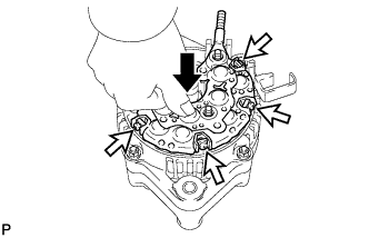
| 2. INSTALL GENERATOR RECTIFIER END FRAME |
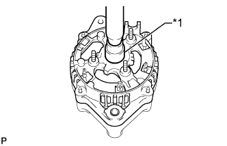
Using a 17 mm socket wrench and press, slowly press on the rectifier end frame.
| *1 | 17 mm Socket Wrench |
Install the cord clip and 4 nuts.
| 3. INSTALL GENERATOR HOLDER WITH RECTIFIER |
Install the 4 rubber insulators to the lead wires.
 | Inside |
While pushing down on the rectifier holder, install it with the 4 screws.
| Push |
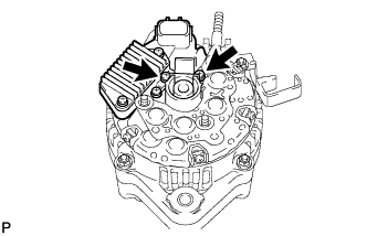
| 4. INSTALL GENERATOR REGULATOR ASSEMBLY |
Install the regulator with the 3 screws.
| 5. INSTALL GENERATOR BRUSH HOLDER ASSEMBLY |
Install the plate seal.

Install the brush holder with the 2 screws.
| Upper |
Install the brush holder cover.
| 6. INSTALL GENERATOR REAR END COVER |
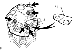
Install the rear end cover and rectifier plate with the bolt and 3 nuts.
| *1 | Rectifier Plate |
Install the terminal insulator with the nut.
| 7. INSTALL VACUUM PUMP ASSEMBLY |
Align the matchmarks and install the vacuum pump with the 4 bolts.
| 1. INSPECT GENERATOR ROTOR ASSEMBLY |
Check the generator rotor for an open circuit.
Measure the resistance according to the value(s) in the table below.
| Tester Connection | Condition | Specified Condition |
| Slip ring - Slip ring | 20°C (68°F) | 2.1 to 2.5 Ω |
| *1 | Slip Ring |
If the result is not as specified, replace the generator rotor assembly.
Check if the generator rotor is grounded.

Measure the resistance according to the value(s) in the table below.
| Tester Connection | Condition | Specified Condition |
| Slip ring - Rotor core | Always | 10 kΩ or higher |
| *1 | Slip Ring |
| *2 | Rotor Core |
If the result is not as specified, replace the generator rotor assembly.
Check that the slip rings are not rough or scored.
If they are rough or scored, replace the generator rotor assembly.

Using a vernier caliper, measure the slip ring diameter.
| *1 | Diameter |
If the diameter is less than the minimum, replace the generator rotor assembly.
Inspect the bearing.
Check that the bearing is not rough or worn.
If necessary, replace the generator rotor assembly.
| 2. INSPECT DRIVE END FRAME |
Check the stator for an open circuit.

Measure the resistance according to the value(s) in the table below.
| Tester Connection | Condition | Specified Condition |
| Coil lead - Coil lead | Always | Below 1 Ω |
| *1 | Coil Lead |
If the result is not as specified, replace the generator assembly.
Check the stator for a short circuit.
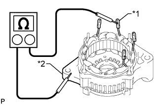
Measure the resistance according to the value(s) in the table below.
| Tester Connection | Condition | Specified Condition |
| Coil lead - Drive end frame | Always | 10 kΩ or higher |
| *1 | Coil Lead |
| *2 | Drive End Frame |
If the result is not as specified, replace the generator assembly.
Inspect the bearing.
Check that the bearing is not rough or worn.
If necessary, replace the generator assembly.
| 3. INSPECT BRUSH HOLDER |

Using a vernier caliper, measure the exposed brush length.
| *1 | Length |
If the exposed length is less than the minimum, replace the brush holder.
| 4. INSPECT GENERATOR HOLDER WITH RECTIFIER |

Check the positive terminal of the rectifier.
| *1 | Positive (+) Terminal |
| *2 | Rectifier Terminal |
Using an ohmmeter, connect one tester probe to the positive (+) terminal and the other to each rectifier terminal.
Reverse the polarity of the tester probes and repeat the step above.
Check that one polarity shows a resistance of below 1 Ω and the other shows a resistance of 10 kΩ or higher.
If the result is not as specified, replace the generator holder with rectifier.

Check the negative terminal of the rectifier.
| *1 | Negative (-) Terminal |
Using an ohmmeter, connect one tester probe to the negative (-) terminal and the other to each rectifier terminal.
Reverse the polarity of the tester probes and repeat the step above.
Check that one polarity shows a resistance of below 1 Ω and the other shows a resistance of 10 kΩ or higher.
If the result is not as specified, replace the generator holder with rectifier.
| 5. INSPECT GENERATOR REGULATOR ASSEMBLY |

Measure the resistance according to the value(s) in the table below.
| Tester Connection | Condition | Specified Condition |
| Terminal F - Terminal B | Always | Below 1 Ω or higher than 10 kΩ |
| *1 | Terminal F |
| *2 | Terminal B |
If the result is not as specified, replace the generator regulator assembly.

Measure the resistance according to the value(s) in the table below.
| Tester Connection | Condition | Specified Condition |
| Terminal F - Terminal E | Always | Below 1 Ω or higher than 10 kΩ |
| *1 | Terminal F |
| *2 | Terminal E |
If the result is not as specified, replace the generator regulator assembly.
| 1. INSPECT GENERATOR WITH VACUUM PUMP ASSEMBLY |
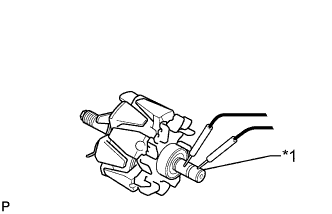
Mount the generator in a vise between aluminum plates.
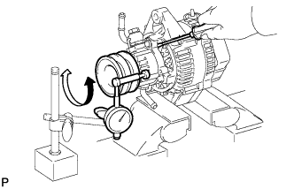
Insert a screwdriver to hold the generator rotor.
Install a bolt and nut to the outside of the pulley so that the bolt head and nut clamp the pulley, and then position a dial indicator as shown in the illustration.
Turn the pulley and measure the backlash between the generator rotor and vacuum pump shaft.
If the backlash is more than the maximum, replace the generator rotor and vacuum pump shaft.
| 2. REMOVE VACUUM PUMP ASSEMBLY |

Place matchmarks as shown in the illustration.
| *a | Matchmark |
Remove the 4 bolts and vacuum pump.
| 3. REMOVE GENERATOR REAR END COVER |

Remove the nut and terminal insulator.
Remove the bolt, 3 nuts, rectifier plate and rear end cover.
| 4. REMOVE GENERATOR BRUSH HOLDER ASSEMBLY |
Remove the brush holder cover.
Remove the 2 screws and brush holder.
Remove the plate seal.
| 5. REMOVE GENERATOR REGULATOR ASSEMBLY |

Remove the 3 screws and generator regulator.
| 6. REMOVE GENERATOR HOLDER WITH RECTIFIER |

Remove the 4 screws and generator holder with rectifier.
Remove the 4 rubber insulators.
| 7. REMOVE GENERATOR RECTIFIER END FRAME |

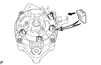
Remove the 4 nuts and cord clip.
| *1 | Cord Clip |

Using SST, remove the rectifier end frame.
| *a | Hold |
| Turn |
Remove the washer from the rotor.
| 8. REMOVE GENERATOR ROTOR ASSEMBLY |

Using SST and a press, press out the rotor.
| 1. DISCONNECT CABLE FROM NEGATIVE BATTERY TERMINAL |
| 2. REMOVE FAN AND GENERATOR V BELT |
Remove the fan and generator V belt (See page ).
| 3. DISCONNECT COOLER COMPRESSOR ASSEMBLY |

Remove the 4 bolts and idle pulley bracket.
Disconnect the connector.
Remove the 3 bolts and disconnect the cooler compressor.
| 4. REMOVE GENERATOR ASSEMBLY |

Remove the terminal cap.
Remove the nut and generator wire.
Disconnect the generator connector.
Disconnect the vacuum pump hose.
Remove the union bolt to disconnect the vacuum pump oil inlet hose and remove the 2 gaskets.
Detach the vacuum pump oil inlet hose from the cord clip.
Disconnect the vacuum pump oil outlet hose.

Remove the 2 bolts and generator.


| 1. CHECK BATTERY CONDITION |
Check the battery for damage and deformation. If severe damage, deformation or leakage is found, replace the battery.
Check the electrolyte quantity of each cell.
For maintenance-free batteries:
For non-maintenance-free batteries:
Turn the ignition switch off and turn on the headlights for 20 to 30 seconds. This removes the surface charge from the battery.
Measure the battery voltage between the negative (-) and positive (+) terminals of the battery.
If the voltage is less than the specification, recharge the battery.
| 2. INSPECT BATTERY TERMINAL AND FUSE |
Check that the battery terminals are not loose or corroded.
If the terminals are corroded, clean the terminals.
Measure the resistance of the H-fuses and fuses.
If the result is not as specified, replace the fuses.
| 3. INSPECT FAN AND GENERATOR V BELT |
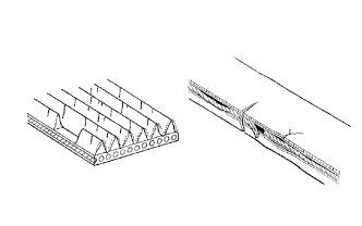
Убедитесь в отсутствии износа, трещин и других признаков повреждения.
При обнаружении следующих дефектов замените вентилятор и поликлиновой ремень генератора.
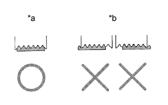
Убедитесь в том, что приводной ремень правильно располагается в углублениях шкива.
| *a | ПРАВИЛЬНО |
| *b | НЕПРАВИЛЬНО |

Убедитесь, что индикаторная метка натяжителя находится в диапазоне A, как показано на рисунке.
| *1 | Метка со стороны кронштейна |
| *2 | Метка со стороны рычага |
| *3 | Поликлиновой ремень вентилятора и генератора |
| *4 | Натяжитель |
Если метка находится вне зоны A, замените поликлиновой ремень вентилятора и генератора.
| 4. INSPECT GENERATOR WIRING |
Visually check the generator wiring.
Check that the wiring is in good condition.
| 5. CHECK FOR ABNORMAL NOISES |
Listen for abnormal noises from the generator.
Check that no abnormal noises are heard from the generator while the engine is running.
| 6. INSPECT CHARGE WARNING LIGHT CIRCUIT |
Turn the ignition switch to ON. Check that the charge warning light comes on.
Start the engine and check that the light goes off.
If the light does not operate as specified, troubleshoot the charge warning light circuit.
| 7. INSPECT CHARGING CIRCUIT WITHOUT LOAD |
Connect a voltmeter and ammeter to the charging circuit as follows.

Disconnect the wire from terminal B of the generator, and then connect it to the negative (-) lead of an ammeter.
| *1 | Battery |
| *2 | Terminal B |
| *3 | Generator |
Connect the positive (+) lead of the ammeter to terminal B of the generator.
Connect the positive (+) lead of a voltmeter to the positive (+) terminal of the battery.
Ground the negative (-) lead of the voltmeter.
Check the charging circuit.
Maintain the engine speed at 2000 rpm and check the reading on the ammeter and voltmeter.
If the voltmeter reading is higher than the standard voltage, replace the generator assembly.
| 8. INSPECT CHARGING CIRCUIT WITH LOAD |
With the engine running at 2000 rpm, turn the high beam headlights on and turn the heater blower switch to the HI position.
Check the reading on the ammeter.
If the ammeter reading is below the standard current, repair the generator.