Задающая Шестерня - Узлы И Детали
Land Cruiser Prado GRJ150 TRJ150 TRJ155 KDJ150 TRJ155 LJ150 - МЕХАНИЧЕСКАЯ ТРАНСМИССИЯ В БЛОКЕ С ГЛАВНОЙ ПЕРЕДАЧЕЙ G52F
ЗАДАЮЩАЯ ШЕСТЕРНЯ - УЗЛЫ И ДЕТАЛИ

1 / 1
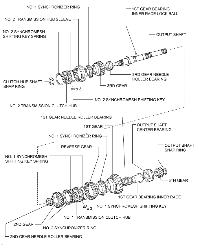
| 1. INSTALL 3RD GEAR NEEDLE ROLLER BEARING |

Coat the needle roller bearing with gear oil and install it to the output shaft.
| 2. INSTALL 3RD GEAR |

Coat the 3rd gear with gear oil and install it to the output shaft.
| 3. INSTALL NO. 1 SYNCHRONIZER RING |

Coat the No. 1 synchronizer ring with gear oil and install it to the 3rd gear.
| 4. INSTALL NO. 2 TRANSMISSION CLUTCH HUB |
Coat the hub sleeve with gear oil and install it to the clutch hub.
 | Front |

Install the 3 synchromesh shifting keys to the clutch hub with the 2 synchromesh shifting key springs.

Using SST and a press, install the No. 2 clutch hub to the output shaft.

Select a clutch hub shaft snap ring that will allow minimal axial play.
| Mark | Thickness |
| C-1 | 1.75 to 1.80 mm (0.0689 to 0.0709 in.) |
| D | 1.80 to 1.85 mm (0.0709 to 0.0728 in.) |
| D-1 | 1.85 to 1.90 mm (0.0728 to 0.0748 in.) |
| E | 1.90 to 1.95 mm (0.0748 to 0.0768 in.) |
| E-1 | 1.95 to 2.00 mm (0.0768 to 0.0787 in.) |
| F | 2.00 to 2.05 mm (0.0787 to 0.0807 in.) |
| F-1 | 2.05 to 2.10 mm (0.0807 to 0.0827 in.) |

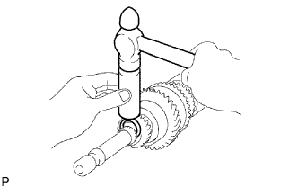
Using a snap ring expander, install the snap ring.
| 5. INSPECT 3RD GEAR THRUST CLEARANCE |

Using a feeler gauge, measure the thrust clearance.
| *1 | 3rd Gear |
| 6. INSTALL 2ND GEAR NEEDLE ROLLER BEARING |

Coat the needle roller bearing with gear oil and install it to the output shaft.
| 7. INSTALL 2ND GEAR |

Coat the 2nd gear with gear oil and install it to the output shaft.
| 8. INSTALL NO. 2 SYNCHRONIZER RING (for 2nd Gear) |

Coat the No. 2 synchronizer ring with gear oil and install it to the 2nd gear.
| 9. INSTALL NO. 1 TRANSMISSION CLUTCH HUB |

Coat the reverse gear with gear oil and install it to the clutch hub.
| Front |
Install the 3 synchromesh shifting keys to the clutch hub with the 2 synchromesh shifting key springs.
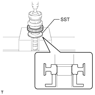
Using SST and a press, install the clutch hub to the output shaft.
| 10. INSTALL NO. 1 SYNCHRONIZER RING (for 1st Gear) |

Coat the synchronizer ring with gear oil and install it to the No. 1 clutch hub.
| 11. INSTALL 1ST GEAR BEARING INNER RACE LOCK BALL |

Coat the lock ball with gear oil and install it to the output shaft.
| 12. INSTALL 1ST GEAR BEARING INNER RACE |

Coat the needle roller bearing with gear oil.
Install the inner race and needle roller bearing to the 1st gear.
| *1 | 1st Gear Bearing Inner Race |
| *2 | 1st Gear Needle Roller Bearing |
| *3 | 1st Gear |
| 13. INSTALL 1ST GEAR |

Coat the 1st gear with gear oil and install it to the output shaft.
| 14. INSTALL OUTPUT SHAFT CENTER BEARING |

Using SST and a press, install the center bearing to the output shaft.
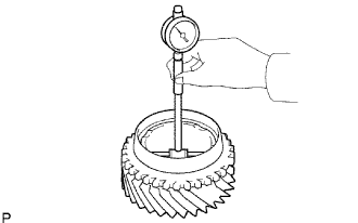
| 15. INSPECT 1ST GEAR THRUST CLEARANCE |

Using a dial indicator, measure the thrust clearance.
| *1 | 1st Gear |
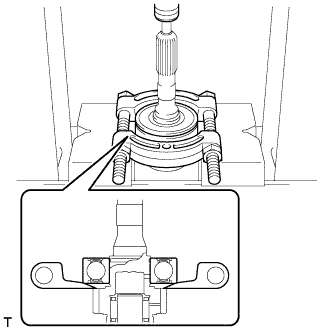
| 16. INSTALL 5TH GEAR |

Using SST and a press, install the 5th gear to the output shaft.

Select a snap ring that will allow minimal axial play.
| Mark | Thickness |
| A | 2.67 to 2.72 mm (0.1052 to 0.1070 in.) |
| B | 2.73 to 2.78 mm (0.1075 to 0.1094 in.) |
| C | 2.79 to 2.84 mm (0.1099 to 0.1118 in.) |
| D | 2.85 to 2.90 mm (0.1123 to 0.1141 in.) |
| E | 2.91 to 2.96 mm (0.1146 to 0.1165 in.) |
| F | 2.97 to 3.02 mm (0.1170 to 0.1188 in.) |
| G | 3.03 to 3.08 mm (0.1193 to 0.1212 in.) |
| H | 3.09 to 3.14 mm (0.1217 to 0.1236 in.) |
| J | 3.15 to 3.20 mm (0.1241 to 0.1259 in.) |
| K | 3.21 to 3.26 mm (0.1264 to 0.1283 in.) |
| L | 3.27 to 3.32 mm (0.1288 to 0.1307 in.) |
Using a brass bar and hammer, tap on the snap ring.
| 17. INSPECT 5TH GEAR THRUST CLEARANCE |

Using a dial indicator, measure the thrust clearance.
| *1 | 5th Gear |
| 18. INSPECT 3RD GEAR THRUST CLEARANCE |
Using a feeler gauge, measure the thrust clearance.
| *1 | 3rd Gear |
| 19. INSPECT 2ND GEAR THRUST CLEARANCE |

Using a dial indicator, measure the thrust clearance.
| *1 | 2nd Gear |
| 20. INSPECT 1ST GEAR THRUST CLEARANCE |
Using a dial indicator, measure the thrust clearance.
| *1 | 1st Gear |
| 21. INSPECT 3RD GEAR RADIAL CLEARANCE |

Using a dial indicator, measure the radial clearance.
| 22. INSPECT 2ND GEAR RADIAL CLEARANCE |

Using a dial indicator, measure the radial clearance.
| 23. INSPECT 1ST GEAR RADIAL CLEARANCE |

Using a dial indicator, measure the radial clearance.
| 1. INSPECT OUTPUT SHAFT |

Using a micrometer, measure the journal diameter of the output shaft journal surface.
| Item | Specified Condition |
| Journal A | 34.984 to 35.000 mm (1.3774 to 1.3779 in.) |
| Journal B | 37.984 to 38.000 mm (1.4955 to 1.4960 in.) |
| Journal C | 30.384 to 30.400 mm (1.1963 to 1.1968 in.) |
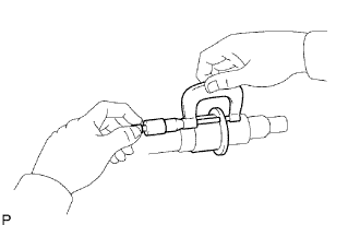
Using a micrometer, measure the flange thickness.
| 2. INSPECT 1ST GEAR BEARING INNER RACE |

Using a micrometer, measure the inner race thickness.
Using a micrometer, measure the outside diameter of the inner race.
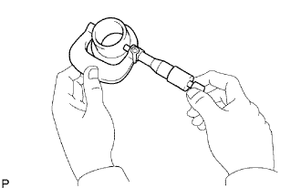
| 3. INSPECT NO. 1 SYNCHRONIZER RING (for 1st Gear) |

Coat the 1st gear cone with gear oil.
Check the braking effect of the No. 1 synchronizer ring.
Install the ring to the shaft cone.
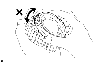
Apply pressure to the ring and attempt to turn it in both directions. Check that the ring locks.

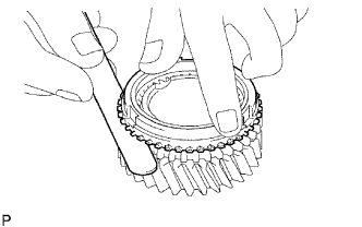
Using a feeler gauge, measure the clearance between the No. 1 synchronizer ring back and 1st gear spline end.
| 4. INSPECT NO. 1 SYNCHRONIZER RING (for 2nd Gear) |
Coat the 2nd gear cone with gear oil.
Check the braking effect of the No. 1 synchronizer ring.
Install the ring to the shaft cone.
Apply pressure to the ring and attempt to turn it in both directions. Check that the ring locks.

Using a feeler gauge, measure the clearance between the No. 1 synchronizer ring back and 2nd gear spline end.
| 5. INSPECT NO. 2 SYNCHRONIZER RING |

Coat the 3rd gear cone with gear oil.
Check the braking effect of the No. 2 synchronizer ring.
Install the ring to the shaft cone.
Apply pressure to the ring and attempt to turn it in both directions. Check that the ring locks.
Using a feeler gauge, measure the clearance between the No. 2 synchronizer ring back and 3rd gear spline end.
| 6. INSPECT REVERSE GEAR |

Using a vernier caliper, measure the clearance between the reverse gear and No. 1 gear shift fork.

Check that the No. 1 transmission clutch hub and reverse gear slide smoothly.
Check that the splines of the reverse gear are not worn down.
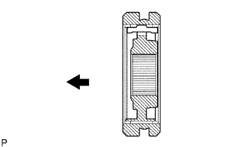
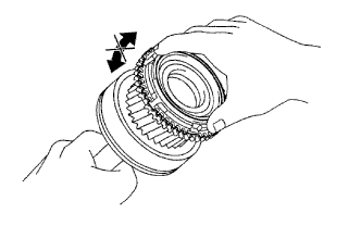
| 7. INSPECT NO. 2 TRANSMISSION HUB SLEEVE |

Using a vernier caliper, measure the No. 2 hub sleeve and No. 2 gear shift fork as shown in the illustration.

Check the sliding condition between the No. 2 hub sleeve and No. 2 clutch hub.
Check that the splines of the No. 2 transmission hub sleeve are not worn down.
| 8. INSPECT 1ST GEAR |

Using a cylinder gauge, measure the inside diameter of the 1st gear.
| 9. INSPECT 2ND GEAR |

Using a cylinder gauge, measure the inside diameter of the 2nd gear.
| 10. INSPECT 3RD GEAR |
Using a cylinder gauge, measure the inside diameter of the 3rd gear.
| 1. INSPECT 5TH GEAR THRUST CLEARANCE |
Using a dial indicator, measure the thrust clearance.
| *1 | 5th Gear |
| 2. INSPECT 1ST GEAR THRUST CLEARANCE |
Using a dial indicator, measure the thrust clearance.
| *1 | 1st Gear |
| 3. INSPECT 2ND GEAR THRUST CLEARANCE |
Using a dial indicator, measure the thrust clearance.
| *1 | 2nd Gear |
| 4. INSPECT 3RD GEAR THRUST CLEARANCE |
Using a feeler gauge, measure the thrust clearance.
| *1 | 3rd Gear |
| 5. INSPECT 1ST GEAR RADIAL CLEARANCE |
Using a dial indicator, measure the radial clearance.
| 6. INSPECT 2ND GEAR RADIAL CLEARANCE |
Using a dial indicator, measure the radial clearance.
| 7. INSPECT 3RD GEAR RADIAL CLEARANCE |
Using a dial indicator, measure the radial clearance.
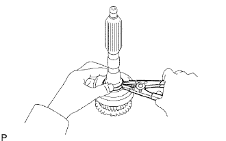
| 8. REMOVE 1ST GEAR |

Using 2 screwdrivers and a hammer, tap off the snap ring from the output shaft.

Using SST and a press, remove the 5th gear, center bearing, 1st gear bearing inner race, 1st gear and 1st gear needle roller bearing from the output shaft.
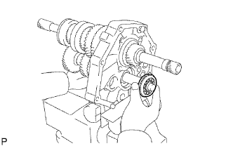
| 9. REMOVE NO. 1 SYNCHRONIZER RING (for 1st Gear) |
Remove the No. 1 synchronizer ring from the No. 1 clutch hub.
| 10. REMOVE 1ST GEAR BEARING INNER RACE LOCK BALL |

Using a magnet hand, remove the lock ball.
| 11. REMOVE 2ND GEAR |

Using SST and a press, remove the reverse gear, No. 1 transmission clutch hub, No. 1 synchronizer ring and 2nd gear.
| 12. REMOVE NO. 2 SYNCHRONIZER RING (for 2nd Gear) |
Remove the No. 2 synchronizer ring from the 2nd gear.
| 13. REMOVE 2ND GEAR NEEDLE ROLLER BEARING |

Remove the needle roller bearing from the output shaft.
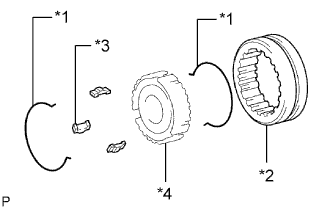
| 14. REMOVE NO. 1 TRANSMISSION CLUTCH HUB |

Remove the 2 synchromesh shifting key springs.
Remove the reverse gear and 3 synchromesh shifting keys from the transmission clutch hub.
| *1 | No. 1 Synchromesh Shifting Key Spring |
| *2 | Reverse Gear |
| *3 | No. 1 Synchromesh Shifting Key |
| *4 | No. 1 Transmission Clutch Hub |
| 15. REMOVE 3RD GEAR |

Using a snap ring expander, remove the snap ring from the output shaft.
Using a press, remove the No. 2 transmission clutch hub and 3rd gear.
| 16. REMOVE NO. 1 SYNCHRONIZER RING |

Remove the No. 1 synchronizer ring from the 3rd gear.
| 17. REMOVE 3RD GEAR NEEDLE ROLLER BEARING |
Remove the needle roller bearing from the output shaft.
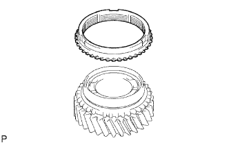
| 18. REMOVE NO. 2 TRANSMISSION CLUTCH HUB |
Remove the 2 synchromesh shifting key springs.
Remove the transmission hub sleeve and 3 synchromesh shifting keys from the transmission clutch hub.
| *1 | No. 2 Synchromesh Shifting Key Spring |
| *2 | No. 2 Transmission Hub Sleeve |
| *3 | No. 2 Synchromesh Shifting Key |
| *4 | No. 2 Transmission Clutch Hub |
| 1. INSTALL INPUT SHAFT FRONT BEARING |

Using SST and a press, install a new front bearing.

Select a snap ring that will allow minimal axial play.
| Mark | Thickness |
| 0 | 2.05 to 2.10 mm (0.0807 to 0.0827 in.) |
| 1 | 2.10 to 2.15 mm (0.0827 to 0.0847 in.) |
| 2 | 2.15 to 2.20 mm (0.0847 to 0.0866 in.) |
| 3 | 2.20 to 2.25 mm (0.0866 to 0.0886 in.) |
| 4 | 2.25 to 2.30 mm (0.0886 to 0.0906 in.) |
| 5 | 2.30 to 2.35 mm (0.0906 to 0.0925 in.) |

Using a snap ring expander, install the snap ring.
| 2. INSTALL INPUT SHAFT BEARING |

Coat the 13 input shaft bearings with MP grease and install them to the input shaft.
| 3. INSTALL NO. 2 SYNCHRONIZER RING |

Coat the No. 2 synchronizer ring with gear oil and install it to the input shaft.
| 1. INSPECT NO. 2 SYNCHRONIZER RING |
Coat the input shaft cone with gear oil.
Check the braking effect of the No. 2 synchronizer ring.
Install the ring to the shaft cone.
Apply pressure to the ring and attempt to turn it in both directions. Check that the ring locks.

Using a feeler gauge, measure the clearance between the No. 2 synchronizer ring back and input shaft spline end.
| 1. REMOVE NO. 2 SYNCHRONIZER RING |
Remove the synchronizer ring.
| 2. REMOVE INPUT SHAFT BEARING |
Remove the 13 input shaft bearings.
| 3. REMOVE INPUT SHAFT FRONT BEARING |
Using a snap ring expander, remove the snap ring.
Using SST and a press, remove the front bearing.

| 1. INSTALL OUTPUT SHAFT ASSEMBLY |

Install the output shaft to the intermediate plate by pushing on the output shaft and tapping on the intermediate plate with a plastic-faced hammer.
Using a snap ring expander, install the snap ring to the center bearing.
| 2. INSTALL INPUT SHAFT ASSEMBLY |

Coat the input shaft and No. 2 synchronizer ring with gear oil, and install them to the output shaft.
| 3. INSTALL COUNTER GEAR ASSEMBLY |
Coat the input shaft and No. 2 synchronizer ring with gear oil.
Temporarily install the counter gear, input shaft and a new center bearing to the intermediate plate.

Using a plastic-faced hammer, install the center bearing to the intermediate plate by tapping the outer race to the counter gear center bearing.
Using a snap ring expander, install the counter shaft center bearing snap ring to the counter shaft center bearing.
| 4. INSTALL OUTPUT SHAFT REAR BEARING RETAINER |
Using a T40 "TORX" socket, install the output shaft rear bearing retainer to the intermediate plate with the 4 screws.
| 5. INSTALL REVERSE IDLER GEAR SUB-ASSEMBLY |
Install the reverse idler gear shaft and reverse idler gear to the intermediate plate.
Install the reverse idler gear shaft stopper to the intermediate plate with the bolt.
| 6. INSTALL REVERSE SHIFT ARM BRACKET |
Install the reverse shift arm bracket to the intermediate plate with the 2 bolts.
| 7. INSTALL 5TH GEAR BEARING INNER RACE LOCK BALL |
Install the lock ball.
| 8. INSTALL 5TH GEAR THRUST WASHER |
Install the 5th gear thrust washer.
| 9. INSTALL NO. 3 TRANSMISSION HUB SLEEVE |
Coat the counter shaft 5th gear with gear oil.


Install the counter 5th gear, counter shaft 5th gear bearing, 3 synchromesh shifting keys, 2 synchromesh shifting key springs and No. 3 transmission hub sleeve.
| *1 | No. 3 Transmission Hub Sleeve |
| *2 | No. 3 Synchromesh Shifting Key Spring |
| *3 | Counter Shaft 5th Gear Bearing |
| *4 | No. 3 Synchromesh Shifting Key |
| *5 | Counter Shaft 5th Gear |
| Front |
| 10. INSTALL COUNTER SHAFT 5TH GEAR |

Install the counter 5th gear bearing to the 5th gear.
Install the counter shaft 5th gear to the counter gear.

Temporarily install the No. 1 synchronizer ring on the No. 5 gear spline piece.

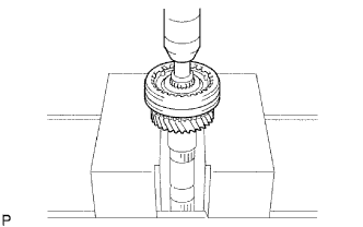
Remove the intermediate plate from the vise.
Stand the transmission as shown in the illustration.

Using a press and 22 mm socket wrench, install the No. 5 gear spline piece with the No. 1 synchronizer ring slots aligned with the shifting keys.
Fix the intermediate plate in a vise between aluminum plates.

Select a snap ring that will allow minimal axial play.
| Mark | Thickness |
| A | 2.80 to 2.85 mm (0.110 to 0.112 in.) |
| B | 2.85 to 2.90 mm (0.112 to 0.114 in.) |
| C | 2.90 to 2.95 mm (0.114 to 0.116 in.) |
| D | 2.95 to 3.00 mm (0.116 to 0.118 in.) |
| E | 3.00 to 3.05 mm (0.118 to 0.120 in.) |
| F | 3.05 to 3.10 mm (0.120 to 0.122 in.) |
| G | 3.10 to 3.15 mm (0.122 to 0.124 in.) |

Using a brass bar and hammer, tap the snap ring to the counter gear.
| 11. INSPECT COUNTER SHAFT 5TH GEAR THRUST CLEARANCE |

Using a feeler gauge, measure the counter shaft 5th gear thrust clearance.
| 12. INSTALL NO. 2 GEAR SHIFT FORK SHAFT |
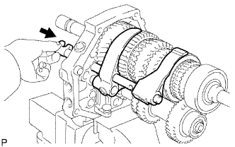
Install the No. 2 gear shift fork and No. 1 gear shift fork.
Pass the No. 2 gear shift fork shaft through the intermediate plate, No. 2 gear shift fork and No. 1 gear shift fork to install it.
Using a brass bar and hammer, tap the shaft snap ring onto the No. 2 gear shift fork shaft.
Install the bolt to the No. 2 gear shift fork.
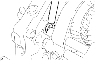
| 13. INSTALL NO. 2 SHIFT INTERLOCK PIN |

Coat the No. 2 shift interlock pin with MP grease and install it to the No. 1 gear shift fork shaft.
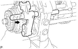
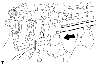
| 14. INSTALL NO. 1 GEAR SHIFT FORK SHAFT |
Coat the No. 1 shift interlock pin with MP grease.

Using a magnet hand, install the No. 1 shift interlock pin to the intermediate plate.
Pass the No. 1 gear shift fork shaft through the intermediate plate and No. 2 gear shift fork to install it.
Install the bolt to the No. 1 shift fork.

Using pliers, install the shaft snap ring to the No. 1 gear shift fork shaft.
| 15. INSTALL REVERSE SHIFT ARM |

Install the shift arm shoe E-ring and the shift arm shoe to the reverse shift arm.

Install the reverse shift arm E-ring and reverse shift fork to the reverse shift arm.
Install the reverse shift arm to the reverse shift arm bracket.
| 16. INSTALL NO. 2 SHIFT INTERLOCK PIN |

Coat the No. 2 shift interlock pin with MP grease, and install it to the No. 3 gear shift fork shaft.
| 17. INSTALL NO. 3 SHIFT INTERLOCK PIN |

Coat the No. 3 shift interlock pin with MP grease.
Using a magnet hand, install the No. 3 shift interlock pin to the intermediate plate.
| 18. INSTALL NO. 3 GEAR SHIFT FORK SHAFT |
Install the No. 3 gear shift fork shaft through the reverse shift fork and intermediate plate.

Install the reverse shift head ring to the reverse shift fork shaft.
Using a 5 mm pin punch and a hammer, tap in the slotted spring pin to the No. 3 shift fork shaft.
| 19. INSTALL NO. 5 GEAR SHIFT FORK SHAFT |
Install the No. 5 gear shift fork shaft and reverse shift head.
Using a 5 mm pin punch and hammer, tap in the slotted spring pin to the No. 3 shift fork shaft.
| 20. INSTALL NO. 4 GEAR SHIFT FORK SHAFT |

Coat the 2 shift detent balls with MP grease.
Using a magnet hand, install the 2 shift detent balls to the intermediate plate.
Pass the No. 4 gear shift fork shaft through the reverse shift fork, intermediate plate and reverse shift head to install it.
Install a new No. 3 gear shift fork with the bolt.
| 21. INSTALL NO. 2 SHIFT DETENT BALL |

Coat the No. 2 detent ball with MP grease.
Install the No. 2 detent ball and compression spring to the intermediate plate.
Coat the spring seat with adhesive.
Using a T40 "TORX" socket, install the spring seat to the intermediate plate.
| 22. INSTALL SHIFT DETENT BALL |
Coat the 3 shift detent balls with MP grease, and then install them and the 3 compression springs to the intermediate plate.
Coat the spring seat and 2 ball plugs with adhesive.
Using a T40 "TORX" socket, install the spring seat and 2 ball plugs to the intermediate plate.
| 23. INSTALL MANUAL TRANSMISSION CASE |

Apply seal packing to the transmission case as shown in the illustration.
| *1 | Seal Packing |

Stand the intermediate plate as shown in the illustration.
Using a plastic-faced hammer, install the transmission case to the intermediate plate as shown in the illustration.
| 24. INSTALL NO. 1 COUNTER GEAR FRONT BEARING SNAP RING |
Using a snap ring expander, install the snap ring to the counter gear front bearing.
| 25. INSTALL FRONT BEARING SHAFT SNAP RING |
Using a snap ring expander, install the snap ring to the input shaft front bearing.
| 26. INSTALL TRANSMISSION FRONT BEARING RETAINER OIL SEAL |

Using SST, press in a new oil seal to the front bearing retainer.
| *a | Oil Seal Depth |
Apply a light coat of MP grease to the lip of the oil seal.
| 27. INSTALL FRONT BEARING RETAINER |
Install a new gasket and the front bearing retainer to the transmission case.
Install the 8 bolts.
| 28. INSTALL TRANSFER ADAPTER OIL SEAL |

Using SST, tap in a new oil seal to the transfer adaptor.
Apply a light coat of MP grease to the lip of the oil seal.
| 29. INSTALL NO. 1 REVERSE RESTRICT PIN ASSEMBLY |
Install the restrict pin to the transfer adaptor.
Using a 5 mm pin punch and hammer, tap in the slotted spring pin to the transfer adaptor.
Using a T40 "TORX" socket, install the plug to the transfer adaptor.
| 30. INSTALL SHIFT AND SELECT LEVER |

Install the shift and select lever and shift lever housing to the transfer adaptor.
| *1 | Shift Lever Housing |
| *2 | Shift and Select Lever |
| 31. INSTALL TRANSFER OIL RECEIVER PIPE |
Install the oil receiver pipe to the transfer adaptor.
| 32. INSTALL TRANSMISSION MAGNET |
Install the magnet to the transfer adaptor.
| 33. INSTALL TRANSFER ADAPTER |

Apply seal packing to the transfer adaptor as shown in the illustration.
| *1 | Seal Packing |

Install the transfer adaptor to the manual transmission case with the 8 bolts.
Install the bolt to the shift lever housing.
| 34. INSTALL SHIFT DETENT BALL |

Coat the shift detent ball with MP grease, and then install it and the compression spring to the transfer adapter.
Using a T40 "TORX" socket, install the spring seat to the transfer adapter.
| 35. INSTALL FLOOR SHIFT CONTROL SHIFT LEVER RETAINER SUB-ASSEMBLY |
Install a new gasket to the transfer adapter.
Install the shift lever retainer with the 4 bolts.
| 36. INSTALL RESTRICT PIN |
Install the 2 restrict pins to the transfer adaptor.
| 37. INSTALL FRONT TRANSMISSION CASE |

Install the front transmission case.
Apply adhesive to the bolt threads.
Install the 9 bolts.
| 38. INSTALL BACK-UP LIGHT SWITCH ASSEMBLY |
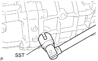
Using SST, install a new gasket and the back-up light switch to the manual transmission case.
| 39. INSTALL CLUTCH RELEASE FORK BOOT |
Install the release fork boot to the front transmission case.
| 40. INSTALL RELEASE FORK SUPPORT |
Install the release fork support to the front transmission case.
| 41. INSTALL CLUTCH RELEASE BEARING ASSEMBLY |

Apply release hub grease to the clutch release bearing, and then install it to the clutch release fork with the clip.
| *a | Release hub grease |
| 42. INSTALL CLUTCH RELEASE FORK SUB-ASSEMBLY |
Install the clutch release fork.

Apply clutch spline grease to the spline of the input shaft.
| *a | Clutch spline grease |
| 43. INSTALL DRAIN PLUG SUB-ASSEMBLY |
Install a new gasket and the drain plug to the transmission case.
| 44. INSTALL MANUAL TRANSMISSION FILLER PLUG |
Install a new gasket and the filler plug to the transmission case.