DESCRIPTION
WIRING DIAGRAM
INSPECTION PROCEDURE
READ VALUE USING INTELLIGENT TESTER (DOOR LOCK POSITION SWITCH)
CHECK WIRELESS ANSWER-BACK OPERATION
CHECK HAZARD WARNING LIGHT OPERATION
PERFORM ACTIVE TEST USING INTELLIGENT TESTER (HAZARD WARNING LIGHT)
CHECK HARNESS AND CONNECTOR (TURN SIGNAL FLASHER - MAIN BODY ECU)
PERFORM ACTIVE TEST USING INTELLIGENT TESTER (WIRELESS DOOR LOCK BUZZER)
CHECK HARNESS AND CONNECTOR (WIRELESS DOOR LOCK BUZZER - MAIN BODY ECU)
REPLACE WIRELESS DOOR LOCK BUZZER
CHECK WIRELESS DOOR LOCK BUZZER OPERATION
WIRELESS DOOR LOCK CONTROL SYSTEM (w/o Entry and Start System) - No Answer-Back
DESCRIPTION
In some cases, the wireless door lock control functions are normal but the hazard warning light or wireless door lock buzzer answer-back function does not operate. In such cases, hazard warning light and wireless door lock buzzer signal outputs from the main body ECU may be malfunctioning.
WIRING DIAGRAM
INSPECTION PROCEDURE
- Start troubleshooting after confirming that the customize status of the answer-back function has been switched on.
| 1.READ VALUE USING INTELLIGENT TESTER (DOOR LOCK POSITION SWITCH) |
Connect the intelligent tester to the DLC3.
Turn the ignition switch to ON.
Turn the intelligent tester on.
Enter the following menus: Body / Main Body / Data List.
Read the Data List according to the display on the intelligent tester.
Main Body| Tester Display | Measurement Item/Range | Normal Condition | Diagnostic Note |
| Back Door Lock Pos SW | Back door lock position switch status / ON or OFF | ON: Back door unlocked
OFF: Back door locked | - |
| FR Door Lock Pos | Front RH side door lock position switch signal / UNLOCK or LOCK | UNLOCK: Front RH side door unlocked
LOCK: Front RH side door locked | - |
| FL Door Lock Pos | Front LH side door lock position switch signal / UNLOCK or LOCK | UNLOCK: Front LH side door unlocked
LOCK: Front LH side door locked | - |
| RR-Door Lock Pos SW | Rear RH side door lock position switch signal / ON or OFF | ON: Rear RH side door unlocked
OFF: Rear RH side door locked | - |
| RL-Door Lock Pos SW | Rear LH side door lock position switch signal / ON or OFF | ON: Rear LH side door unlocked
OFF: Rear LH side door locked | - |
- OK:
- The intelligent tester display changes as shown in the table according to door lock operation.
| | GO TO POWER DOOR LOCK CONTROL SYSTEM ()
|
|
|
| 2.CHECK WIRELESS ANSWER-BACK OPERATION |
Check the wireless answer-back operation using the wireless door lock control function.
Result| Result | Proceed to |
| Only hazard warning light answer-back does not occur | A |
| Only wireless door lock buzzer answer-back does not occur | B |
| 3.CHECK HAZARD WARNING LIGHT OPERATION |
Check that the hazard warning lights flash continuously when the hazard warning signal switch is pressed.
- OK:
- Hazard warning lights flash continuously.
| 4.PERFORM ACTIVE TEST USING INTELLIGENT TESTER (HAZARD WARNING LIGHT) |
Operate the intelligent tester according to the steps on the display and select "Active Test" ().
Main Body| Tester Display | Test Part | Control Range | Diagnostic Note |
| Hazard | Turn signal flasher relay | ON/OFF | - |
- OK:
- The hazard warning lights can be turned on and off using the intelligent tester.
| OK | |
| |
| REPLACE MAIN BODY ECU (COWL SIDE JUNCTION BLOCK LH) |
|
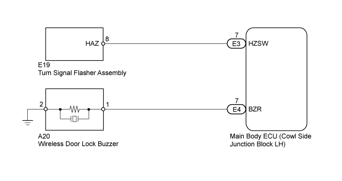
| 5.CHECK HARNESS AND CONNECTOR (TURN SIGNAL FLASHER - MAIN BODY ECU) |
Disconnect the E19 flasher connector.
Disconnect the E3 main body ECU connector.
Measure the resistance according to the value(s) in the table below.
- Standard Resistance:
| Tester Connection | Condition | Specified Condition |
| E19-8 (HAZ) - E3-7 (HZSW) | Always | Below 1 Ω |
| E19-8 (HAZ) - Body ground | Always | 10 kΩ or higher |
| | REPAIR OR REPLACE HARNESS OR CONNECTOR |
|
|
| OK | |
| |
| REPLACE MAIN BODY ECU (COWL SIDE JUNCTION BLOCK LH) |
|
| 6.PERFORM ACTIVE TEST USING INTELLIGENT TESTER (WIRELESS DOOR LOCK BUZZER) |
Operate the intelligent tester according to the steps on the display and select "Active Test" ().
Main Body| Tester Display | Test Part | Control Range | Diagnostic Note |
| Wireless Buzzer | Wireless door lock buzzer | ON/OFF | - |
- OK:
- The wireless door lock buzzer can be turned on and off using the intelligent tester.
| OK | |
| |
| REPLACE MAIN BODY ECU (COWL SIDE JUNCTION BLOCK LH) |
|
| 7.CHECK HARNESS AND CONNECTOR (WIRELESS DOOR LOCK BUZZER - MAIN BODY ECU) |
Disconnect the A20 buzzer connector.
Disconnect the E4 main body ECU connector.
Measure the resistance according to the value(s) in the table below.
- Standard Resistance:
| Tester Connection | Condition | Specified Condition |
| A20-1 - E4-7 (BZR) | Always | Below 1 Ω |
| A20-2 - Body ground | Always | Below 1 Ω |
| A20-1 - Body ground | Always | 10 kΩ or higher |
| | REPAIR OR REPLACE HARNESS OR CONNECTOR |
|
|
| 8.REPLACE WIRELESS DOOR LOCK BUZZER |
Temporarily replace the wireless door lock buzzer with a new or normally functioning one ().
| 9.CHECK WIRELESS DOOR LOCK BUZZER OPERATION |
Check that the wireless door lock buzzer sounds by operating the wireless door lock function.
- OK:
- Wireless door lock buzzer sounds.
| | REPLACE MAIN BODY ECU (COWL SIDE JUNCTION BLOCK LH) |
|
|
| OK | |
| |
| END (WIRELESS DOOR LOCK BUZZER IS DEFECTIVE) |
|