DESCRIPTION
WIRING DIAGRAM
INSPECTION PROCEDURE
PERFORM ACTIVE TEST USING INTELLIGENT TESTER (SECURITY INDICATOR)
CHECK HARNESS AND CONNECTOR (CLOCK - MAIN BODY ECU AND BODY GROUND)
REPLACE CLOCK ASSEMBLY (SECURITY INDICATOR LIGHT)
THEFT DETERRENT SYSTEM (w/o Entry and Start System) - Security Indicator Light Circuit
DESCRIPTION
When the theft deterrent system is in the disarmed state, the security indicator will flash continuously if the immobiliser system is set, or not illuminate if the immobiliser system is not set.
When the theft deterrent system is in the armed state, the immobiliser system is automatically set and the security indicator will flash continuously.
When the theft deterrent system is in the arming preparation state or alarm sounding state, the main body ECU (cowl side junction block assembly LH) causes the security indicator to be illuminated.
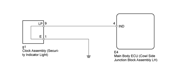
WIRING DIAGRAM
INSPECTION PROCEDURE
| 1.PERFORM ACTIVE TEST USING INTELLIGENT TESTER (SECURITY INDICATOR) |
Connect the intelligent tester to the DLC3.
Turn the ignition switch to ON.
Turn the intelligent tester on.
Enter the following menus: Body / Main Body / Active Test.
According to the display on the intelligent tester, perform the Active Test.
Main Body| Tester Display | Test Part | Control Range | Diagnostic Note |
| Security Indicator | Security indicator | ON / OFF | - |
- OK:
- Security indicator illuminates.
| OK | |
| |
| REPLACE MAIN BODY ECU (COWL SIDE JUNCTION BLOCK ASSEMBLY LH) |
|
| 2.CHECK HARNESS AND CONNECTOR (CLOCK - MAIN BODY ECU AND BODY GROUND) |
Disconnect the g1 clock assembly connector.
Disconnect the E4 main body ECU connector.
Measure the resistance according to the value(s) in the table below.
- Standard Resistance:
| Tester Connection | Condition | Specified Condition |
| g1-9 (LP) - E4-4 (IND) | Always | Below 1 Ω |
| g1-1 (E) - Body ground | Always | Below 1 Ω |
| g1-9 (LP) - Body ground | Always | 10 kΩ or higher |
| | REPAIR OR REPLACE HARNESS OR CONNECTOR |
|
|
| 3.REPLACE CLOCK ASSEMBLY (SECURITY INDICATOR LIGHT) |
Temporarily replace the clock assembly (security indicator light) with a new or normally functioning one ().
When the theft deterrent system is in the arming preparation state, check that the security indicator light is illuminated.
- OK:
- Security indicator light is illuminated.
| | REPLACE MAIN BODY ECU (COWL SIDE JUNCTION BLOCK ASSEMBLY LH) |
|
|
| OK | |
| |
| END (CLOCK ASSEMBLY WAS DEFECTIVE) |
|