Land Cruiser URJ200 URJ202 GRJ200 VDJ200 - SUPPLEMENTAL RESTRAINT SYSTEMS
CHECK PASSENGER AIRBAG ON/OFF INDICATOR CONDITION
CHECK CONNECTION OF CONNECTORS
CHECK PASSENGER AIRBAG ON/OFF INDICATOR
CHECK PASSENGER AIRBAG ON/OFF INDICATOR CIRCUIT
CHECK INSTRUMENT PANEL WIRE (CENTER AIRBAG SENSOR - NO. 2 INSTRUMENT PANEL WIRE)
CHECK NO. 2 INSTRUMENT PANEL WIRE (INSTRUMENT PANEL WIRE - NO. 5 INSTRUMENT PANEL WIRE)
CHECK CONNECTION OF CONNECTORS
CHECK PASSENGER AIRBAG ON/OFF INDICATOR CIRCUIT
CHECK PASSENGER AIRBAG ON/OFF INDICATOR (SOURCE VOLTAGE)
CHECK PASSENGER AIRBAG ON/OFF INDICATOR
CHECK INSTRUMENT PANEL WIRE (CENTER AIRBAG SENSOR - NO. 2 INSTRUMENT PANEL WIRE)
CHECK NO. 2 INSTRUMENT PANEL WIRE (INSTRUMENT PANEL WIRE - NO. 5 INSTRUMENT PANEL WIRE)
DTC B1660/43 Passenger Airbag ON/OFF Indicator Circuit Malfunction
DESCRIPTION
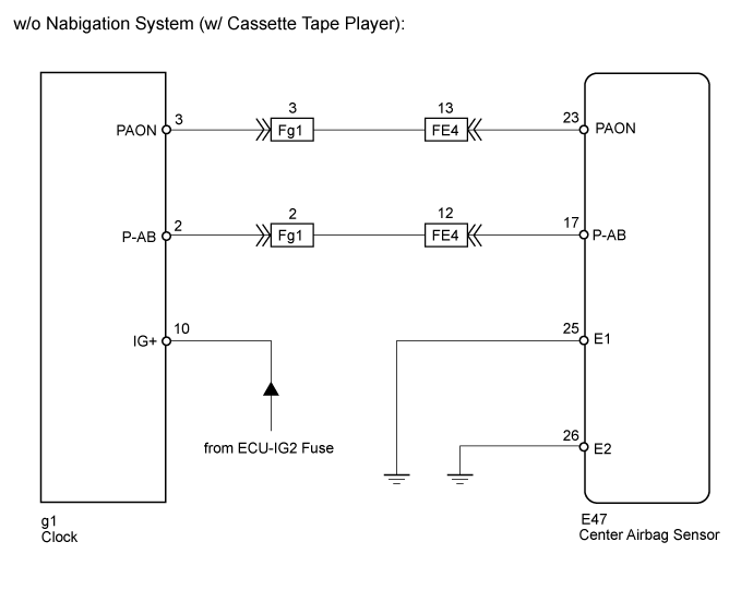
The passenger airbag ON/OFF indicator circuit consists of the center airbag sensor and the passenger airbag ON/OFF indicator.
The passenger airbag ON/OFF indicator indicates the operation condition of the front passenger airbag, front passenger side knee airbag, front seat airbag RH and front seat outer belt RH.
DTC B1660/43 is stored when a malfunction is detected in the passenger airbag ON/OFF indicator circuit.
| DTC Code | DTC Detection Condition | Trouble Area |
| B1660/43 | When one of the following conditions is met: The center airbag sensor receives an open circuit signal, a short circuit to ground signal or a short circuit to B+ signal in the passenger airbag ON/OFF indicator circuit for 2 seconds. A passenger airbag ON/OFF indicator malfunction. A center airbag sensor malfunction. |
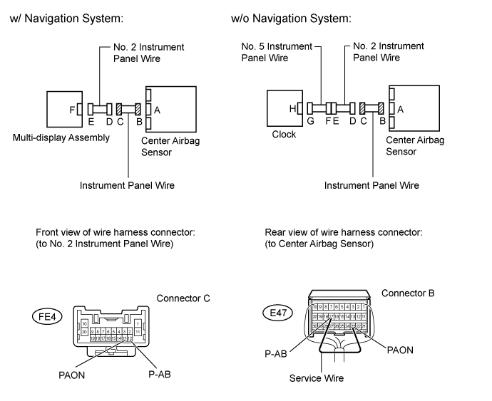
Instrument panel wire Multi-display assembly*1 Clock*2 Center airbag sensor assembly No. 2 instrument panel wire No. 5 instrument panel wire*2 |
- HINT:
- *1: w/ Navigation System
- *2: w/o Navigation System
WIRING DIAGRAM


INSPECTION PROCEDURE
- NOTICE:
| 1.CHECK PASSENGER AIRBAG ON/OFF INDICATOR CONDITION |
Turn the ignition switch to ON.
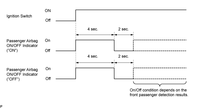
Check the passenger airbag ON/OFF indicator operation.
- HINT:
- Refer to the normal condition of the passenger airbag ON/OFF indicator ().
| Result | Proceed to |
| Always on | A |
| Off | B |
|
| ||||
| A | |
| 2.CHECK CONNECTION OF CONNECTORS |
Turn the ignition switch off.
Disconnect the cable from the negative (-) battery terminal, and wait for at least 90 seconds.
Check that the connectors are properly connected to the center airbag sensor and the multi-display assembly or clock.
- OK:
- The connectors are properly connected.
|
| ||||
| OK | |
| 3.CHECK CONNECTORS |
Disconnect the connectors from the center airbag sensor and the multi-display assembly or clock.
Check that the connectors (on the center airbag sensor side and multi-display assembly side or clock side) are not damaged.
- OK:
- The connectors are not deformed or damaged.
|
| ||||
| OK | |
| 4.CHECK PASSENGER AIRBAG ON/OFF INDICATOR |
Connect the connector to the multi-display assembly or clock.
Connect the cable to the negative (-) battery terminal, and wait for at least 2 seconds.
Turn the ignition switch to ON.
Check the passenger airbag ON/OFF indicator operation.
- OK:
- The passenger airbag ON/OFF indicator does not come on.
|
| ||||
| OK | |
| 5.CHECK CENTER AIRBAG SENSOR |

Connect the connector to the center airbag sensor.
Connect the cable to the negative (-) battery terminal, and wait for at least 2 seconds.
Turn the ignition switch to ON, and wait for at least 60 seconds.
Clear the DTCs ().
Turn the ignition switch off.
Turn the ignition switch to ON, and wait for at least 60 seconds.
Check for DTCs ().
- OK:
- DTC B1660 is not output.
- HINT:
- Codes other than DTC B1660 may be output at this time, but they are not related to this check.
|
| ||||
| OK | ||
| ||
| 6.CHECK PASSENGER AIRBAG ON/OFF INDICATOR CIRCUIT |
Turn the ignition switch off.

Disconnect the cable from the negative (-) battery terminal, and wait for at least 90 seconds.
Disconnect the connector from the center airbag sensor and multi-display assembly or clock.
Connect the cable to the negative (-) battery terminal, and wait for at least 2 seconds.
Measure the voltage according to the value(s) in the table below.
- Standard Voltage:
w/ Navigation System Tester Connection Switch Condition Specified Condition F79-20 (ARON) - Body ground Ignition switch ON Below 1 V F79-8 (AIR) - Body ground Ignition switch ON Below 1 V w/o Navigation System Tester Connection Switch Condition Specified Condition g1-3 (PAON) - Body ground Ignition switch ON Below 1 V g1-2 (P-AB) - Body ground Ignition switch ON Below 1 V
Turn the ignition switch off.
Disconnect the cable from the negative (-) battery terminal, and wait for at least 90 seconds.
Using a service wire, connect terminals 23 (PAON) and 17 (P-AB) of connector B.
- NOTICE:
- Do not forcibly insert the service wire into the terminals of the connector when connecting a service wire.
Measure the resistance according to the value(s) in the table below.
- Standard Resistance:
w/ Navigation System Tester Connection Condition Specified Condition F79-20 (ARON) - F79-8 (AIR) Always Below 1 Ω w/o Navigation System Tester Connection Condition Specified Condition g1-3 (PAON) - g1-2 (P-AB) Always Below 1 Ω
Disconnect the service wire from connector B.
Measure the resistance according to the value(s) in the table below.
- Standard Resistance:
w/ Navigation System Tester Connection Condition Specified Condition F79-20 (ARON) - F79-8 (AIR) Always 1 MΩ or higher F79-20 (ARON) - Body ground Always 1 MΩ or higher F79-8 (AIR) - Body ground Always 1 MΩ or higher w/o Navigation System Tester Connection Condition Specified Condition g1-3 (PAON) - g1-2 (P-AB) Always 1 MΩ or higher g1-3 (PAON) - Body ground Always 1 MΩ or higher g1-2 (P-AB) - Body ground Always 1 MΩ or higher
| Result | Proceed to |
| OK (w/ Navigation System) | A |
| OK (w/o Navigation System) | B |
| NG | C |
|
| ||||
|
| ||||
| A | ||
| ||
| 7.CHECK INSTRUMENT PANEL WIRE (CENTER AIRBAG SENSOR - NO. 2 INSTRUMENT PANEL WIRE) |
Disconnect the instrument panel wire connector from the No. 2 instrument panel wire.

Connect the cable to the negative (-) battery terminal, and wait for at least 2 seconds.
Measure the voltage according to the value(s) in the table below.
- Standard Voltage:
Tester Connection Switch Condition Specified Condition FE4-13 (PAON) - Body ground Ignition switch ON Below 1 V FE4-12 (P-AB) - Body ground Ignition switch ON Below 1 V
Turn the ignition switch off.
Disconnect the cable from the negative (-) battery terminal, and wait for at least 90 seconds.
Using a service wire, connect terminals 23 (PAON) and 17 (P-AB) of connector B.
- NOTICE:
- Do not forcibly insert the service wire into the terminals of the connector when connecting a service wire.
Measure the resistance according to the value(s) in the table below.
- Standard Resistance:
Tester Connection Condition Specified Condition FE4-13 (PAON) - FE4-12 (P-AB) Always Below 1 Ω
Disconnect the service wire from connector B.
Measure the resistance according to the value(s) in the table below.
- Standard Resistance:
Tester Connection Condition Specified Condition FE4-13 (PAON) - FE4-12 (P-AB) Always 1 MΩ or higher FE4-13 (PAON) - Body ground Always 1 MΩ or higher FE4-12 (P-AB) - Body ground Always 1 MΩ or higher
| Result | Proceed to |
| OK (w/ Navigation System) | A |
| OK (w/o Navigation System) | B |
| NG | C |
|
| ||||
|
| ||||
| A | ||
| ||
| 8.CHECK NO. 2 INSTRUMENT PANEL WIRE (INSTRUMENT PANEL WIRE - NO. 5 INSTRUMENT PANEL WIRE) |
Disconnect the No. 2 instrument panel wire connector from the No. 5 instrument panel wire.
Connect the cable to the negative (-) battery terminal, and wait for at least 2 seconds.
Measure the voltage according to the value(s) in the table below.
- Standard Voltage:
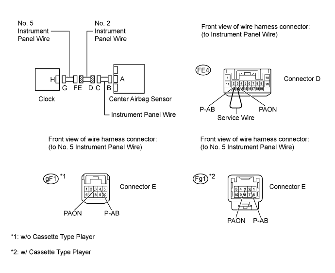
w/o Cassette Type Player Tester Connection Switch Condition Specified Condition gF1-3 (PAON) - Body ground Ignition switch ON Below 1 V gF1-4 (P-AB) - Body ground Ignition switch ON Below 1 V w/ Cassette Type Player Tester Connection Switch Condition Specified Condition Fg1-3 (PAON) - Body ground Ignition switch ON Below 1 V Fg1-2 (P-AB) - Body ground Ignition switch ON Below 1 V
Turn the ignition switch off.
Disconnect the cable from the negative (-) battery terminal, and wait for at least 90 seconds.
Using a service wire, connect terminals 13 (PAON) and 12 (P-AB) of connector D.
- NOTICE:
- Do not forcibly insert the service wire into the terminals of the connector when connecting a service wire.
Measure the resistance according to the value(s) in the table below.
- Standard Resistance:
w/o Cassette Type Player Tester Connection Condition Specified Condition gF1-3 (PAON) - gF1-4 (P-AB) Always Below 1 Ω w/ Cassette Type Player Tester Connection Condition Specified Condition Fg1-3 (PAON) - Fg1-2 (P-AB) Always Below 1 Ω
Disconnect the service wire from connector D.
Measure the resistance according to the value(s) in the table below.
- Standard Resistance:
w/o Cassette Type Player Tester Connection Condition Specified Condition gF1-3 (PAON) - gF1-4 (P-AB) Always 1 MΩ or higher gF1-3 (PAON) - Body ground Always 1 MΩ or higher gF1-4 (P-AB) - Body ground Always 1 MΩ or higher w/ Cassette Type Player Tester Connection Condition Specified Condition Fg1-3 (PAON) - Fg1-2 (P-AB) Always 1 MΩ or higher Fg1-3 (PAON) - Body ground Always 1 MΩ or higher Fg1-2 (P-AB) - Body ground Always 1 MΩ or higher
|
| ||||
| OK | ||
| ||
| 9.CHECK CONNECTION OF CONNECTORS |
Turn the ignition switch off.
Disconnect the cable from the negative (-) battery terminal, and wait for at least 90 seconds.
Check that the connectors are properly connected to the center airbag sensor and the multi-display assembly or clock.
- OK:
- The connectors are properly connected.
|
| ||||
| OK | |
| 10.CHECK CONNECTORS |
Disconnect the connectors from the center airbag sensor and the multi-display assembly or clock.
Check that the connectors (on the center airbag sensor side and multi-display assembly side or clock side) are not damaged.
- OK:
- The connectors are not deformed or damaged.
|
| ||||
| OK | |
| 11.CHECK PASSENGER AIRBAG ON/OFF INDICATOR CIRCUIT |
Connect the cable to the negative (-) battery terminal, and wait for at least 2 seconds.
Measure the voltage according to the value(s) in the table below.
- Standard Voltage:
w/ Navigation System Tester Connection Switch Condition Specified Condition F79-20 (ARON) - Body ground Ignition switch ON Below 1 V F79-8 (AIR) - Body ground Ignition switch ON Below 1 V w/o Navigation System Tester Connection Switch Condition Specified Condition g1-3 (PAON) - Body ground Ignition switch ON Below 1 V g1-2 (P-AB) - Body ground Ignition switch ON Below 1 V
Turn the ignition switch off.
Disconnect the cable from the negative (-) battery terminal, and wait for at least 90 seconds.
Using a service wire, connect terminals 23 (PAON) and 17 (P-AB) of connector B.
- NOTICE:
- Do not forcibly insert the service wire into the terminals of the connector when connecting a service wire.
Measure the resistance according to the value(s) in the table below.
- Standard Resistance:
w/ Navigation System Tester Connection Condition Specified Condition F79-20 (ARON) - F79-8 (AIR) Always Below 1 Ω w/o Navigation System Tester Connection Condition Specified Condition g1-3 (PAON) - g1-2 (P-AB) Always Below 1 Ω
Disconnect the service wire from connector B.
Measure the resistance according to the value(s) in the table below.
- Standard Resistance:
w/ Navigation System Tester Connection Condition Specified Condition F79-20 (ARON) - F79-8 (AIR) Always 1 MΩ or higher F79-20 (ARON) - Body ground Always 1 MΩ or higher F79-8 (AIR) - Body ground Always 1 MΩ or higher w/o Navigation System Tester Connection Condition Specified Condition g1-3 (PAON) - g1-2 (P-AB) Always 1 MΩ or higher g1-3 (PAON) - Body ground Always 1 MΩ or higher g1-2 (P-AB) - Body ground Always 1 MΩ or higher
|
| ||||
| OK | |
| 12.CHECK PASSENGER AIRBAG ON/OFF INDICATOR (SOURCE VOLTAGE) |
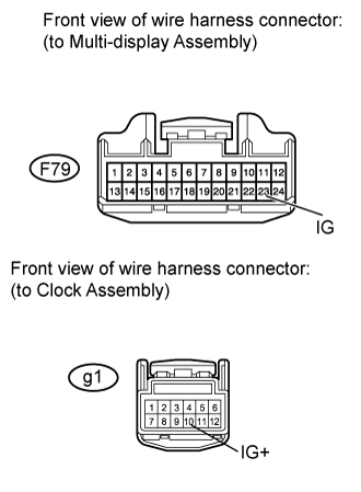
Turn the ignition switch off.
Connect the connectors to the center airbag sensor.
Connect the cable to the negative (-) battery terminal, and wait for at least 2 seconds.
Measure the voltage according to the value(s) in the table below.
- Standard Voltage:
w/ Navigation System Tester Connection Switch Condition Specified Condition F64-3 (IG) - Body ground Ignition switch ON 11 to 14 V w/o Navigation System Tester Connection Switch Condition Specified Condition g1-10 (IG+) - Body ground Ignition switch ON 11 to 14 V
| Result | Proceed to |
| OK | A |
| NG (w/ Navigation System) | B |
| NG (w/o Navigation System) | C |
|
| ||||
|
| ||||
| A | |
| 13.CHECK PASSENGER AIRBAG ON/OFF INDICATOR |

Turn the ignition switch off.
Disconnect the cable from the negative (-) battery terminal, and wait for at least 90 seconds.
Connect the connector to the multi-display assembly or clock.
Disconnect the connectors from the center airbag sensor.
Connect the cable to the negative (-) battery terminal, and wait for at least 2 seconds.
Check the indicator according to the table below.
- OK:
Tester Connection Switch Condition Passenger airbag ON/OFF indicator E47-23 (PAON) - Body ground Ignition switch ON "ON" comes on E47-17 (P-AB) - Body ground Ignition switch ON "OFF" comes on
| Result | Proceed to |
| OK | A |
| NG (w/ Navigation System) | B |
| NG (w/o Navigation System) | C |
|
| ||||
|
| ||||
| A | |
| 14.CHECK CENTER AIRBAG SENSOR |
Turn the ignition switch off.
Disconnect the cable from the negative (-) battery terminal, and wait for at least 90 seconds.
Connect the connectors to the center airbag sensor.
Connect the cable to the negative (-) battery terminal, and wait for at least 2 seconds.
Turn the ignition switch to ON, and wait for at least 60 seconds.
Clear the DTCs ().
Turn the ignition switch off.
Turn the ignition switch to ON, and wait for at least 60 seconds.
Check for DTCs ().
- OK:
- DTC B1660 is not output.
- HINT:
- Codes other than DTC B1660 may be output at this time, but they are not related to this check.
|
| ||||
| OK | ||
| ||
| 15.CHECK INSTRUMENT PANEL WIRE (CENTER AIRBAG SENSOR - NO. 2 INSTRUMENT PANEL WIRE) |
Disconnect the instrument panel wire connector from the No. 2 instrument panel wire.
Connect the cable to the negative (-) battery terminal, and wait for at least 2 seconds.
Measure the voltage according to the value(s) in the table below.
- Standard Voltage:
Tester Connection Switch Condition Specified Condition FE4-13 (PAON) - Body ground Ignition switch ON Below 1 V FE4-12 (P-AB) - Body ground Ignition switch ON Below 1 V
Turn the ignition switch off.
Disconnect the cable from the negative (-) battery terminal, and wait for at least 90 seconds.
Using a service wire, connect terminals 23 (PAON) and 17 (P-AB) of connector B.
- NOTICE:
- Do not forcibly insert the service wire into the terminals of the connector when connecting a service wire.
Measure the resistance according to the value(s) in the table below.
- Standard Resistance:
Tester Connection Condition Specified Condition FE4-13 (PAON) - FE4-12 (P-AB) Always Below 1 Ω
Disconnect the service wire from connector B.
Measure the resistance according to the value(s) in the table below.
- Standard Resistance:
Tester Connection Condition Specified Condition FE4-13 (PAON) - FE4-12 (P-AB) Always 1 MΩ or higher FE4-13 (PAON) - Body ground Always 1 MΩ or higher FE4-12 (P-AB) - Body ground Always 1 MΩ or higher
| Result | Proceed to |
| OK (w/ Navigation System) | A |
| OK (w/o Navigation System) | B |
| NG | C |
|
| ||||
|
| ||||
| A | ||
| ||
| 16.CHECK NO. 2 INSTRUMENT PANEL WIRE (INSTRUMENT PANEL WIRE - NO. 5 INSTRUMENT PANEL WIRE) |
Disconnect the No. 2 instrument panel wire connector from the No. 5 instrument panel wire.
Connect the cable to the negative (-) battery terminal, and wait for at least 2 seconds.
Measure the voltage according to the value(s) in the table below.
- Standard Voltage:
w/o Cassette Type Player Tester Connection Switch Condition Specified Condition gF1-3 (PAON) - Body ground Ignition switch ON Below 1 V gF1-4 (P-AB) - Body ground Ignition switch ON Below 1 V w/ Cassette Type Player Tester Connection Switch Condition Specified Condition Fg1-3 (PAON) - Body ground Ignition switch ON Below 1 V Fg1-2 (P-AB) - Body ground Ignition switch ON Below 1 V
Turn the ignition switch off.
Disconnect the cable from the negative (-) battery terminal, and wait for at least 90 seconds.
Using a service wire, connect terminals 13 (PAON) and 12 (P-AB) of connector D.
- NOTICE:
- Do not forcibly insert the service wire into the terminals of the connector when connecting a service wire.
Measure the resistance according to the value(s) in the table below.
- Standard Resistance:
w/o Cassette Type Player Tester Connection Condition Specified Condition gF1-3 (PAON) - gF1-4 (P-AB) Always Below 1 Ω w/ Cassette Type Player Tester Connection Condition Specified Condition Fg1-3 (PAON) - Fg1-2 (P-AB) Always Below 1 Ω
Disconnect the service wire from connector D.
Measure the resistance according to the value(s) in the table below.
- Standard Resistance:
w/o Cassette Type Player Tester Connection Condition Specified Condition gF1-3 (PAON) - gF1-4 (P-AB) Always 1 MΩ or higher gF1-3 (PAON) - Body ground Always 1 MΩ or higher gF1-4 (P-AB) - Body ground Always 1 MΩ or higher w/ Cassette Type Player Tester Connection Condition Specified Condition Fg1-3 (PAON) - Fg1-2 (P-AB) Always 1 MΩ or higher Fg1-3 (PAON) - Body ground Always 1 MΩ or higher Fg1-2 (P-AB) - Body ground Always 1 MΩ or higher
|
| ||||
| OK | ||
| ||