Land Cruiser URJ200 URJ202 GRJ200 VDJ200 - LIGHTING EXT
CHECK HARNESS AND CONNECTOR (ENGINE SWITCH - MAIN BODY ECU AND BODY GROUND)
LIGHTING SYSTEM - Engine Switch Illumination Circuit
DESCRIPTION
The engine switch illumination is controlled by the main body ECU. The operation and condition of this control are described below (Light control switch is OFF).
| Operation | Condition |
| Fade in | When any of the following conditions is met, the engine switch illumination fades in. The key enters any actuation area around the doors when the engine switch is off and all the doors are closed. Any door is opened. Any door is unlocked when the engine switch is off and all the doors are closed. The engine switch is turned from on (ACC) to off when all the doors are closed. |
| Fade out immediately | When either of the following conditions is met, the engine switch illumination fades out. The engine switch is turned from off to on (ACC) or on (IG) when all the doors are closed. All the doors are locked when the engine switch is off. |
| Illuminate for approximately 15 seconds, and then fade out | All the doors are closed when the engine switch is off. |
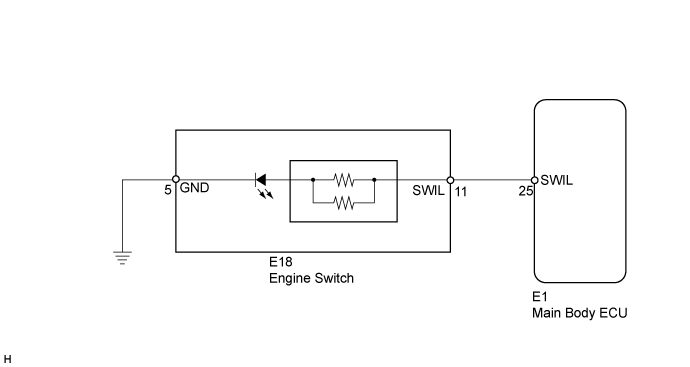
WIRING DIAGRAM
INSPECTION PROCEDURE
| 1.INSPECT ENGINE SWITCH |
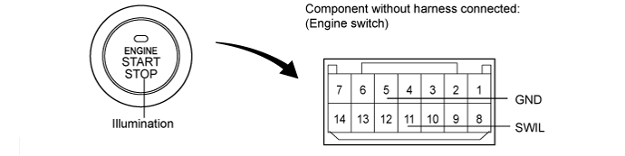
Remove the engine switch ().
Apply battery voltage to the engine switch.
Check that the illumination comes on.
- OK:
Measurement Condition Specified Condition Battery positive (+) → Terminal 11 (SWIL)
Battery negative (-) → Terminal 5 (GND)Engine switch illumination comes on
|
| ||||
| OK | |
| 2.CHECK HARNESS AND CONNECTOR (ENGINE SWITCH - MAIN BODY ECU AND BODY GROUND) |
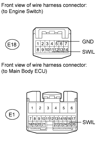
Disconnect the E1 ECU connector.
Disconnect the E18 engine switch connector.
Measure the resistance according to the value(s) in the table below.
- Standard Resistance:
Tester Connection Condition Specified Condition E1-11 (SWIL) - E1-25 (SWIL) Always Below 1 Ω E18-5 (GND) - Body ground E1-11 (SWIL) - Body ground Always 10 kΩ or higher
|
| ||||
| OK | ||
| ||