DESCRIPTION
WIRING DIAGRAM
INSPECTION PROCEDURE
READ VALUE USING INTELLIGENT TESTER (POSITION SWITCH LH)
CHECK DTC OUTPUT
INSPECT LOWER TAIL GATE LOCK ASSEMBLY LH
CHECK HARNESS AND CONNECTOR (LOWER TAIL GATE LOCK ASSEMBLY LH - NO. 2 MAIN BODY ECU AND BODY GROUND)
DTC B225C Tail Gate Panel Position Switch LH
DESCRIPTION
The No. 2 main body ECU receives the close position switch signal from the lower tail gate lock assembly LH and detects the open/closed status of the lower tail gate. DTC B225C is stored when the No. 2 main body ECU receives a close position switch malfunction signal from the lower tail gate lock assembly LH.
| DTC Code | DTC Detection Condition | Trouble Area |
| B225C |
A close position switch malfunction (open or short circuit) signal from the lower tail gate lock LH is received. |
Lower tail gate lock assembly LH
Harness or connector
No. 2 main body ECU
|
WIRING DIAGRAM
INSPECTION PROCEDURE
| 1.READ VALUE USING INTELLIGENT TESTER (POSITION SWITCH LH) |
Check the Data List for proper functioning of the close position switch ().
Body No. 4| Tester Display | Measurement Item/Range | Normal Condition | Diagnostic Note |
| Position Switch LH |
Close position switch LH signal / ON or OFF |
ON: Lower tail gate closed
OFF: Lower tail gate open | - |
- OK:
- The display is as specified in the normal condition.
Starting with the lower tail gate closed, open and close the lower tail gate 6 times.
Starting with the lower tail gate closed, open and close the lower tail gate 6 times.
Recheck for DTCs ().
- OK:
- DTC B225C is not output.
| | REPLACE NO. 2 MAIN BODY ECU ()
|
|
|
| OK | |
| |
| USE SIMULATION METHOD TO CHECK ()
|
|
| 3.INSPECT LOWER TAIL GATE LOCK ASSEMBLY LH |
Remove the lower tail gate lock assembly LH ().
Inspect the lower tail gate lock assembly LH ().
| | REPLACE LOWER TAIL GATE LOCK ASSEMBLY LH ()
|
|
|
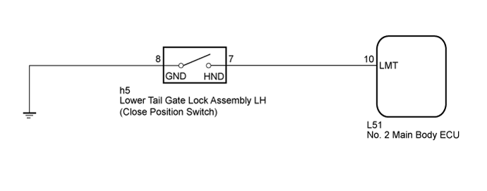
| 4.CHECK HARNESS AND CONNECTOR (LOWER TAIL GATE LOCK ASSEMBLY LH - NO. 2 MAIN BODY ECU AND BODY GROUND) |
Disconnect the h5 lower tail gate lock assembly LH connector.
Disconnect the L51 No. 2 main body ECU connector.
Measure the resistance according to the value(s) in the table below.
- Standard Resistance:
| Tester Connection | Condition | Specified Condition |
| h5-7 (HND) - L51-10 (LMT) | Always | Below 1 Ω |
| h5-8 (GND) - Body ground | Always | Below 1 Ω |
| h5-7 (HND) - Body ground | Always | 10 kΩ or higher |
| | REPAIR OR REPLACE HARNESS OR CONNECTOR |
|
|
| OK | |
| |
| REPLACE NO. 2 MAIN BODY ECU ()
|
|