Land Cruiser URJ200 URJ202 GRJ200 VDJ200 - DOOR / HATCH
BACK DOOR (for Double Swing Out Type) - ADJUSTMENT

- NOTICE:
| *1 | Centering Bolt |
| *2 | Standard Bolt |
| 1. INSPECT BACK DOOR PANEL SUB-ASSEMBLY RH (for RH Side) |
Check that the clearance measurements of areas A to P are within the standard ranges.
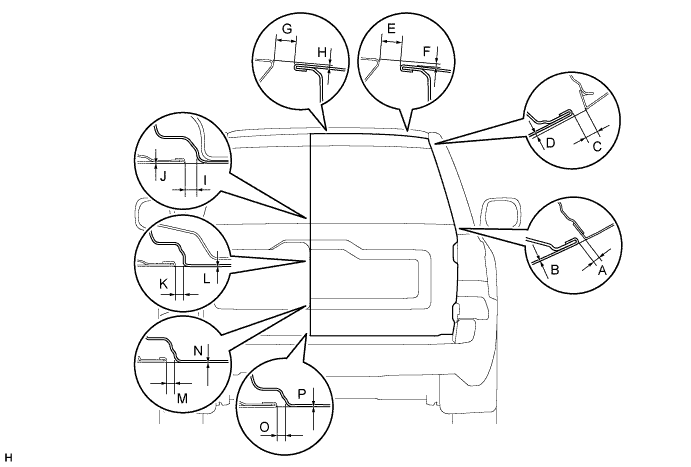
- Standard:
Area Specified Condition Area Specified Condition A 4.6 to 8.6 mm (0.181 to 0.339 in.) B -2 to 2 mm (-0.0787 to 0.0787 in.) C 6.0 to 10.0 mm (0.236 to 0.394 in.) D -0.9 to 3.1 mm (-0.0354 to 0.122 in.) E 11.3 to 14.3 mm (0.445 to 0.563 in.) F 0.5 to 3.5 mm (0.0197 to 0.138 in.) G 11.3 to 14.3 mm (0.445 to 0.563 in.) H 0 to 3.0 mm (0 to 0.118 in.) I 3.5 to 7.5 mm (0.138 to 0.295 in.) J -2 to 2 mm (-0.0787 to 0.0787 in.) K 3.5 to 7.5 mm (0.138 to 0.295 in.) L -2 to 2 mm (-0.0787 to 0.0787 in.) M 3.5 to 7.5 mm (0.138 to 0.295 in.) N -1.8 to 2.2 mm (-0.0709 to 0.0866 in.) O 3.5 to 7.5 mm (0.138 to 0.295 in.) P -2 to 2 mm (-0.0787 to 0.0787 in.)
| 2. REMOVE BACK DOOR UPPER LOCK STRIKER COVER (for RH Side) |

Detach the 4 claws and remove the back door upper lock striker cover.
| 3. ADJUST BACK DOOR PANEL SUB-ASSEMBLY RH (for RH Side) |

Loosen the hinge bolts on the back door panel and adjust the back door panel position.
Tighten the hinge bolts on the back door panel after the adjustment.
- Torque:
- 31 N*m{ 316 kgf*cm, 23 ft.*lbf}

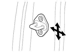
Adjust the back door lock striker position by slightly loosening the bolts and hitting the back door lock striker with a plastic-faced hammer.
Tighten the bolts after the adjustment.
- Torque:
- 29 N*m{ 296 kgf*cm, 21 ft.*lbf}

Using a T40 "TORX" socket wrench, remove the 2 bolts and striker.
Select a back door lock striker shim so that the clearance measurements are within the specified range.
- HINT:
- There are 2 types of back door lock striker shims (0.5 mm and 2.0 mm).
| *1 | Back Door Lock Striker Shim |
Using a T40 "TORX" socket wrench, install the striker with the 2 bolts.
- HINT:
- Mark sure that the yellow marking is facing up when installing the striker.
- Torque:
- 23 N*m{ 235 kgf*cm, 17 ft.*lbf}
| 4. INSTALL BACK DOOR UPPER LOCK STRIKER COVER (for RH Side) |
Attach the 4 claws to install the back door upper lock striker cover.
| 5. INSPECT BACK DOOR PANEL SUB-ASSEMBLY LH (for LH Side) |
Check that the clearance measurements of areas A to P are within the standard ranges.

- Standard:
Area Specified Condition Area Specified Condition A 4.6 to 8.6 mm (0.181 to 0.339 in.) B -2 to 2 mm (-0.0787 to 0.0787 in.) C 6.0 to 10.0 mm (0.236 to 0.394 in.) D -0.9 to 3.1 mm (-0.0354 to 0.122 in.) E 11.3 to 14.3 mm (0.445 to 0.563 in.) F 0.3 to 3.3 mm (0.0118 to 0.130 in.) G 11.3 to 14.3 mm (0.445 to 0.563 in.) H 0 to 3.0 mm (0 to 0.118 in.) I 3.5 to 7.5 mm (0.138 to 0.295 in.) J -2 to 2 mm (-0.0787 to 0.0787 in.) K 3.5 to 7.5 mm (0.138 to 0.295 in.) L -2 to 2 mm (-0.0787 to 0.0787 in.) M 3.5 to 7.5 mm (0.138 to 0.295 in.) N -1.8 to 2.2 mm (-0.0709 to 0.0866 in.) O 3.5 to 7.5 mm (0.138 to 0.295 in.) P -2 to 2 mm (-0.0787 to 0.0787 in.)
| 6. ADJUST BACK DOOR PANEL SUB-ASSEMBLY LH (for LH Side) |

Loosen the hinge bolts on the back door panel and adjust the back door panel position.
Tighten the hinge bolts on the back door panel after the adjustment.
- Torque:
- 31 N*m{ 316 kgf*cm, 23 ft.*lbf}
Using a T40 "TORX" socket, adjust the back door lock striker plate position by slightly loosening the bolts and hitting the back door lock striker plate with a plastic-faced hammer.
Using a T40 "TORX" socket, tighten the bolts after the adjustment.
- Torque:
- 23 N*m{ 235 kgf*cm, 17 ft.*lbf}