Land Cruiser URJ200 URJ202 GRJ200 VDJ200 - SUSPENSION CONTROL
CHECK ACCELERATION SENSOR (DATA LIST)
CHECK HARNESS AND CONNECTOR (ACCELERATION SENSOR - SUSPENSION CONTROL ECU)
DTC C1715 Front Acceleration Sensor RH Malfunction
DTC C1716 Front Acceleration Sensor LH Malfunction
DTC C1717 Rear Acceleration Sensor Malfunction
DTC C1796 Front Acceleration Sensor RH Malfunction (Test Mode DTC)
DTC C1797 Front Acceleration Sensor LH Malfunction (Test Mode DTC)
DTC C1798 Rear Acceleration Sensor Malfunction (Test Mode DTC)
DESCRIPTION
The acceleration sensor (up and down G sensor) detects the upward and downward acceleration of the vehicle, and outputs it as a voltage to the suspension control ECU. Up and down G sensors are installed in 3 locations: 1) the suspension control ECU, 2) the driver side instrument panel, and 3) the passenger side instrument panel. Each up and down G sensor independently detects the upward and downward acceleration. During a test mode inspection, the suspension control ECU reads the fluctuations in the signal of each sensor. When the sensor cannot detect +/-1.96 m/s2 for 1 second or more during test mode, DTCs C1796, C1797 and C1798 are stored.
| DTC Code | Detection Condition | Trouble Area |
| C1715 C1796 | When either of the following conditions is met: With the engine switch on (IG), a voltage of 4.7 V or higher, or 0.3 V or less at the front acceleration sensor RH is detected for 1 second. When there is a front acceleration sensor RH power supply voltage malfunction. | Harness or connector Front acceleration sensor RH Suspension control ECU |
| C1716 C1797 | When either of the following conditions is met: With the engine switch on (IG), a voltage of 4.7 V or higher, or 0.3 V or less at the front acceleration sensor LH is detected for 1 second. When there is a front acceleration sensor LH power supply voltage malfunction. | Harness or connector Front acceleration sensor LH Suspension control ECU |
| C1717 C1798 | When either of the following conditions is met: With the engine switch on (IG), a voltage of 4.7 V or higher, or 0.3 V or less at the rear acceleration sensor is detected for 1 second. When there is a rear acceleration sensor power supply voltage malfunction. | Suspension control ECU (Houses rear acceleration sensor) |
WIRING DIAGRAM

INSPECTION PROCEDURE
- NOTICE:
| 1.CHECK ACCELERATION SENSOR (DATA LIST) |
Turn the engine switch off.
Connect the intelligent tester to the DLC3.
Turn the engine switch on (IG) and the tester on.
Enter the following menus: Chassis / AHC / Data List.
According to the display on the tester, read the Data List.
| Tester Display | Measurement Item/Range | Normal Condition | Diagnostic Note |
| (Up & Down)G Sensor FR | G (up and down) front acceleration sensor RH reading/ min.: -1045.29 m/s2 max.: 1045.26 m/s2 | 0 +/-0.98 m/s2 at still condition | Reading changes when vehicle (FR) is bounced |
| (Up & Down)G Sensor FL | G (up and down) front acceleration sensor LH reading/ min.: -1045.29 m/s2 max.: 1045.26 m/s2 | 0 +/-0.98 m/s2 at still condition | Reading changes when vehicle (FL) is bounced |
| (Up & Down)G Sensor Rear | G (up and down) rear acceleration sensor reading/ min.: -1045.29 m/s2 max.: 1045.26 m/s2 | 0 +/-0.98 m/s2 at still condition | Reading changes when vehicle (rear) is bounced |
- OK:
- Reading changes when vehicle is bounced.
|
| ||||
| OK | |
| 2.RECONFIRM DTC OUTPUT |
Clear the DTCs ().
Perform a road test.
Check for DTCs.
| Result | Proceed to |
| DTC is output | A |
| DTC is not output | B |
|
| ||||
| A | |
| 3.CHECK HARNESS AND CONNECTOR (ACCELERATION SENSOR - SUSPENSION CONTROL ECU) |
- NOTICE:
- When inspecting the wire harnesses between the suspension control ECU and acceleration sensors, it is difficult to determine the malfunctioning area if there is a sensor power supply malfunction. Therefore, disconnect the connectors for the acceleration sensors (front RH, front LH), the fluid temperature sensor, and fluid pressure sensor on the ECU side.
Check the front acceleration sensor RH side: (C1715)

Disconnect the K34 and K35 ECU connectors.
Disconnect the L35 sensor connector.
Measure the resistance according to the value(s) in the table below.
- Standard Resistance:
Tester Connection Condition Specified Condition L35-1 (SGFR) - K34-24 (SGFR) Always Below 1 Ω L35-2 (SGG) - K34-14 (SGG1) Always Below 1 Ω L35-3 (SGB) - K34-15 (SGB1) Always Below 1 Ω K34-24 (SGFR) - Body ground Always 10 kΩ or higher K34-14 (SGG1) - Body ground Always 10 kΩ or higher K34-15 (SGB1) - Body ground Always 10 kΩ or higher
Check the front acceleration sensor LH side: (C1716)
Disconnect the K34 and K35 ECU connectors.
Disconnect the K37 sensor connector.
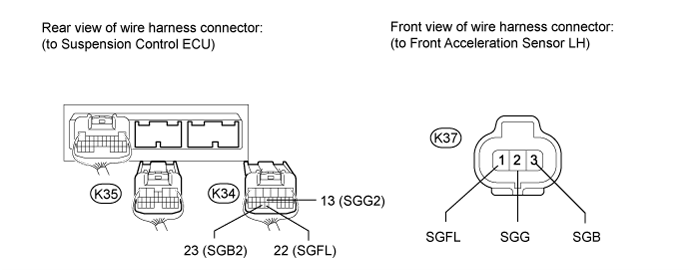
Measure the resistance according to the value(s) in the table below.
- Standard Resistance:
Tester Connection Condition Specified Condition K37-1 (SGFL) - K34-22 (SGFL) Always Below 1 Ω K37-2 (SGG) - K34-13 (SGG2) Always Below 1 Ω K37-3 (SGB) - K34-23 (SGB2) Always Below 1 Ω K34-22 (SGFL) - Body ground Always 10 kΩ or higher K34-13 (SGG2) - Body ground Always 10 kΩ or higher K34-23 (SGB2) - Body ground Always 10 kΩ or higher
|
| ||||
| OK | |
| 4.INSPECT ACCELERATION SENSOR |

Turn the engine switch off.
Remove the front acceleration sensor ().
- NOTICE:
- Do not drop the acceleration sensor. If it is dropped, replace it with a new one.
Connect 3 1.5 V dry cell batteries in series.
Connect the positive (+) end of the batteries to terminal 3 (SGB) of the acceleration sensor and the negative (-) end of the batteries to terminal 2 (SGG). Then measure the voltage between terminal 1 (SGFR*1, SGFL*2) and terminal 2 (SGG).
- HINT:
- *1: for RH
- *2: for LH
- NOTICE:
- Do not apply a voltage of more than 6 V.
- HINT:
- The voltage may differ according to the amount that the sensor is tilted.
- Standard Voltage:
for RH Tester Connection Condition Specified Condition 1 (SGFR) - 2 (SGG) Sensor stationary Approx. 2.0 to 2.5 V Sensor is tilted Change between approx. 0.9 to 2.3 V for LH Tester Connection Condition Specified Condition 1 (SGFL) - 2 (SGG) Sensor stationary Approx. 2.0 to 2.5 V Sensor is tilted Change between approx. 0.9 to 2.3 V
|
| ||||
| OK | ||
| ||