DESCRIPTION
WIRING DIAGRAM
INSPECTION PROCEDURE
INSPECT CAN COMMUNICATION SYSTEM
CHECK HARNESS AND CONNECTOR (POWER STEERING ECU - BATTERY AND BODY GROUND)
PERFORM ACTIVE TEST USING GTS (METER/GAUGE SYSTEM)
POWER STEERING SYSTEM (for 1VD-FTV with DPF) - Power Steering Warning Light Circuit
DESCRIPTION
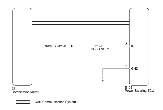
The power steering ECU is connected to the combination meter via CAN communication. If the power steering ECU detects a malfunction, the power steering warning light comes on. At this time, the vehicle enters fail-safe mode.
WIRING DIAGRAM
INSPECTION PROCEDURE
- Inspect the fuses for circuits related to this system before performing the following inspection procedure.
| 1.INSPECT CAN COMMUNICATION SYSTEM |
Check for DTCs of the CAN communication system.
for LHD
Refer to the following procedures ().
for RHD
Refer to the following procedures ().
Result| Result | Proceed to |
| DTC is not output. | A |
| DTC is output. | for LHD | B |
| for RHD | C |
| | GO TO CAN COMMUNICATION SYSTEM (HOW TO PROCEED WITH TROUBLESHOOTING) ()
|
|
|
| | GO TO CAN COMMUNICATION SYSTEM (HOW TO PROCEED WITH TROUBLESHOOTING) ()
|
|
|
| 2.CHECK HARNESS AND CONNECTOR (POWER STEERING ECU - BATTERY AND BODY GROUND) |
Disconnect the power steering ECU connector.
Measure the voltage according to the value(s) in the table below.
- Standard Voltage:
| Tester Connection | Switch Condition | Specified Condition |
| E102-5 (IG) - Body ground | Engine switch on (IG) | 11 to 14 V |
Measure the resistance according to the value(s) in the table below.
- Standard Resistance:
| Tester Connection | Condition | Specified Condition |
| E102-3 (GND) - Body ground | Always | Below 1 Ω |
Text in Illustration| *a | Front view of wire harness connector
(to Power Steering ECU) |
| | REPAIR OR REPLACE HARNESS OR CONNECTOR |
|
|
| 3.PERFORM ACTIVE TEST USING GTS (METER/GAUGE SYSTEM) |
Connect the GTS to the DLC3.
Turn the engine switch on (IG) and turn the GTS on.
Perform the Active Test of the combination meter using GTS ().
Combination Meter| Tester Display | Test Part | Control Range | Diagnostic Note |
| PPS Indicator | Power steering warning light | ON or OFF | Perform the test with the vehicle stopped and the engine idling. |
Check that the power steering warning light operates in accordance with the Active Test.
- Reconnect the connectors and restore the vehicle to its previous condition before checking the combination meter.
- OK:
- The power steering warning light turns on and off in accordance with GTS operation.
| | INSPECT METER/GAUGE SYSTEM (HOW TO PROCEED WITH TROUBLESHOOTING) ()
|
|
|
| OK | |
| |
| REPLACE POWER STEERING ECU ASSEMBLY ()
|
|
