DESCRIPTION
WIRING DIAGRAM
INSPECTION PROCEDURE
CHECK HARNESS AND CONNECTOR (COMBINATION METER ASSEMBLY - BATTERY AND BODY GROUND)
CAN COMMUNICATION SYSTEM (for RHD) - Combination Meter ECU Communication Stop Mode
DESCRIPTION
| Detection Item | Symptom | Trouble Area |
| Combination Meter ECU Communication Stop Mode | Either condition is met:
"Combination Meter" is not displayed on the "Bus Check" screen.
"Combination Meter ECU Communication Stop Mode" in "DTC Combination Table" applies.
| Power source or inside of combination meter assembly
Combination meter assembly
|
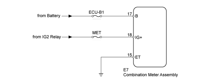
WIRING DIAGRAM
INSPECTION PROCEDURE
- Inspect the fuses for circuits related to this system before performing the following inspection procedure.
| 1.CHECK HARNESS AND CONNECTOR (COMBINATION METER ASSEMBLY - BATTERY AND BODY GROUND) |
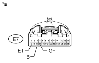
Disconnect the E7 combination meter assembly connector.
Measure the resistance according to the value(s) in the table below.
- Standard Resistance:
| Tester Connection | Condition | Specified Condition |
| E7-15 (ET) - Body ground | Always | Below 1 Ω |
Measure the voltage according to the value(s) in the table below.
- Standard Voltage:
| Tester Connection | Condition | Specified Condition |
| E7-17 (B) - Body ground | Always | 11 to 14 V |
| E7-18 (IG+) - Body ground | Ignition switch ON | 11 to 14 V |
Text in Illustration| *a | Front view of wire harness connector
(to Combination Meter Assembly) |
Result| Result | Proceed to |
| OK (w/ Multi-information Display) | A |
| OK (w/o Multi-information Display) | B |
| NG | C |
| | REPLACE COMBINATION METER ASSEMBLY ()
|
|
|
| | REPAIR OR REPLACE HARNESS OR CONNECTOR |
|
|
| A | |
| |
| REPLACE COMBINATION METER ASSEMBLY ()
|
|