Land Cruiser URJ200 URJ202 GRJ200 VDJ200 - 3UR-FE ENGINE CONTROL
SFI SYSTEM - FREEZE FRAME DATA
| DESCRIPTION |
Freeze frame data records the engine conditions (fuel system, calculated load, engine coolant temperature, fuel trim, engine speed, vehicle speed, etc.) when a malfunction is detected. When troubleshooting, it can help determine if the vehicle was moving or stationary, the engine was warmed up or not, the air-fuel ratio was Lean or Rich, and other data from the time the malfunction occurred.
- HINT:
- If it is impossible to duplicate the problem even though a DTC is output, confirm the freeze frame data.
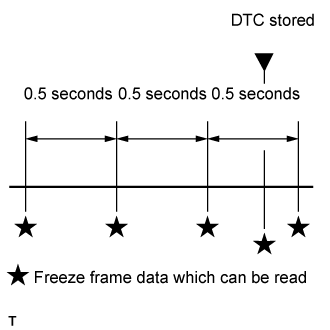
3 data sets before the DTC was stored.
1 data set when the DTC was stored.
1 data set after the DTC was stored.
These data sets can be used to simulate the condition of the vehicle around the time of the occurrence of the malfunction. The data may assist in identifying the cause of the malfunction, and in judging whether it was temporary or not.
| LIST OF FREEZE FRAME DATA |
| Tester Display | Measurement Item | Diagnostic Note |
| Vehicle Speed | Vehicle speed | Speed indicated on speedometer. |
| Engine Speed | Engine speed | - |
| Calculate Load | Calculated load | Calculated load by ECM. |
| Vehicle Load | Vehicle load | - |
| MAF | Mass air flow volume | If approximately 0.0 gm/s: Mass air flow meter power source circuit open or short. VG circuit open or short. E2G circuit open. |
| Atmosphere Pressure | Atmosphere pressure | - |
| Coolant Temp | Engine coolant temperature | If -40°C (-40°F), sensor circuit open. If 140°C (284°F) or more, sensor circuit shorted. |
| Intake Air | Intake air temperature | If -40°C (-40°F), sensor circuit open. If 140°C (284°F) or more, sensor circuit shorted. |
| Engine Run Time | Accumulated engine running time | - |
| Initial Engine Coolant Temp | Engine coolant temperature at engine start | - |
| Initial Intake Air Temp | Intake air temperature at engine start | - |
| Battery Voltage | Battery voltage | - |
| Accel Sens. No.1 Volt % | Absolute Accelerator Pedal Position (APP) No. 1 | - |
| Accel Sens. No.2 Volt % | Absolute APP No. 2 | - |
| Throttle Sensor Volt % | Throttle sensor positioning | - |
| Throttl Sensor #2 Volt % | Throttle sensor positioning #2 | - |
| Throttle Sensor Position | Throttle position | - |
| Throttle Motor DUTY | Throttle actuator | - |
| Throttle Position | Throttle Position | For use when engine stall, starting problems or rough idle is present. |
| ISC Flow | Flow rate calculated using information from each sensor | For use when engine stall, starting problems or rough idle is present. |
| ISC Position | Requested opening amount calculated using ISC control | For use when engine stall, starting problems or rough idle is present. |
| ISC Feedback Value | ISC feedback compensation amount | For use when engine stall, starting problems or rough idle is present. |
| ISC Learning Value | ISC learned compensation amount | For use when engine stall, starting problems or rough idle is present. |
| Electric Load Feedback Val | Compensation flow rate according to electrical load | For use when engine stall, starting problems or rough idle is present. |
| Air Conditioner FB Val | Compensation flow rate according to air conditioner load | For use when engine stall, starting problems or rough idle is present. |
| PS Feedback Val | Compensation flow rate according to power steering load | For use when engine stall, starting problems or rough idle is present. |
| Low Revolution Control | Low engine speed control operation state | For use when engine stall, starting problems or rough idle is present. |
| Neutral Control | Neutral control operation state | For use when engine stall, starting problems or rough idle is present. |
| N Range Status | Shift lever N status | For use when engine stall, starting problems or rough idle is present. |
| Eng Stall Control FB Flow | Intake air compensation flow rate | For use when engine stall, starting problems or rough idle is present. |
| Deposit Loss Flow | Flow loss due to deposits | For use when engine stall, starting problems or rough idle is present. |
| Fuel Pump Duty | Fuel Pump Duty | - |
| Injector (Port) | Injection period of No. 1 cylinder | - |
| Injection Volum (Cylinder 1) | Injection volume | - |
| EVAP (Purge) VSV | EVAP purge VSV duty ratio | - |
| Evap Purge Flow | Ratio of evaporative purge flow to intake air volume | - |
| Purge Density Learn Value | Learning value of purge density | - |
| EVAP Purge VSV | EVAP Purge VSV | - |
| Purge Cut VSV Duty | Purge cut VSV duty | - |
| Target Air-Fuel Ratio | Ratio compared to stoichiometric level | - |
| AF Lambda B1S1 | Fuel trim at A/F sensor (for Bank 1 Sensor 1) | - |
| AF Lambda B2S1 | Fuel trim at A/F sensor (for Bank 2 Sensor 1) | - |
| AFS Voltage B1S1 | A/F sensor output (for Bank 1 Sensor 1) | Performing Control the Injection Volume or Control the Injection Volume for A/F Sensor function of Active Test enables technician to check output voltage of sensor. |
| AFS Voltage B2S1 | A/F sensor output (for Bank 2 Sensor 1) | Performing Control the Injection Volume or Control the Injection Volume for A/F Sensor function of Active Test enables technician to check output voltage of sensor. |
| AFS Current B1S1 | A/F sensor current (for Bank 1 Sensor 1) | - |
| AFS Current B2S1 | A/F sensor current (for Bank 2 Sensor 1) | - |
| A/F Heater Duty #1 | A/F heater duty ratio (for Bank 1 Sensor 1) | - |
| A/F Heater Duty #2 | A/F heater duty ratio (for Bank 2 Sensor 1) | - |
| O2S B1S2 | Heated oxygen sensor output (for Bank 1 Sensor 2) | Performing Control the Injection Volume or Control the Injection Volume for A/F Sensor function of Active Test enables technician to check output voltage of sensor. |
| O2S B2S2 | Heated oxygen sensor output (for Bank 2 Sensor 2) | Performing Control the Injection Volume or Control the Injection Volume for A/F Sensor function of Active Test enables technician to check output voltage of sensor. |
| O2S Impedance B1S2 | Sub heated oxygen sensor impedance (for Bank 1 Sensor 2) | - |
| O2S Impedance B2S2 | Sub heated oxygen sensor impedance (for Bank 2 Sensor 2) | - |
| O2 Heater B1S2 | Heated oxygen sensor heater (for Bank 1 Sensor 2) | - |
| O2 Heater B2S2 | Heated oxygen sensor heater (for Bank 2 Sensor 2) | - |
| O2 Heater Curr Val B1S2 | Heated oxygen sensor current (for Bank 1 Sensor 2) | - |
| O2 Heater Curr Val B2S2 | Heated oxygen sensor current (for Bank 2 Sensor 2) | - |
| Short FT #1 | Short-term fuel trim | Short-term fuel compensation used to maintain air-fuel ratio at stoichiometric air-fuel ratio. |
| Long FT #1 | Long-term fuel trim | Overall fuel compensation carried out in long-term to compensate a continual deviation of short-term fuel trim from central value. |
| A/F Learn Value Idle #1 | Air fuel ratio learn value area of idle (for Bank 1) | Learning is performed when idling with the engine warmed up (engine coolant temperature is 75°C [167°F] or higher). |
| A/F Learn Value Low #1 | Air fuel ratio learn value area of low load (for Bank 1) | Learning is performed when driving with the engine warmed up (engine coolant temperature is 75°C [167°F] or higher) and operating in the low load range (when the range of engine loads is divided into four parts). |
| A/F Learn Value Mid1 #1 | Air fuel ratio learn value area of middle load 1 (for Bank 1) | Learning is performed when driving with the engine warmed up (engine coolant temperature is 75°C [167°F] or higher) and operating in the mid-size load range closer to the low load range (when the range of engine loads is divided into four parts). |
| A/F Learn Value Mid2 #1 | Air fuel ratio learn value area of middle load 2 (for Bank 1) | Learning is performed when driving with the engine warmed up (engine coolant temperature is 75°C [167°F] or higher) and operating in the mid-size load range closer to the high load range (when the range of engine loads is divided into four parts). |
| A/F Learn Value High #1 | Air fuel ratio learn value area of high load (for Bank 1) | Learning is performed when driving with the engine warmed up (engine coolant temperature is 75°C [167°F] or higher) and operating in the high load range (when the range of engine loads is divided into four parts). |
| Total FT #1 | Total fuel trim | - |
| Short FT #2 | Short-term fuel trim | Short-term fuel compensation used to maintain air-fuel ratio at stoichiometric air-fuel ratio. |
| Long FT #2 | Long-term fuel trim | Overall fuel compensation carried out in long-term to compensate a continual deviation of short-term fuel trim from central value. |
| A/F Learn Value Idle #2 | Air fuel ratio learn value area of idle (for Bank 2) | Learning is performed when idling with the engine warmed up (engine coolant temperature is 75°C [167°F] or higher). |
| A/F Learn Value Low #2 | Air fuel ratio learn value area of low load (for Bank 2) | Learning is performed when driving with the engine warmed up (engine coolant temperature is 75°C [167°F] or higher) and operating in the low load range (when the range of engine loads is divided into four parts). |
| A/F Learn Value Mid1 #2 | Air fuel ratio learn value area of middle load 1 (for Bank 2) | Learning is performed when driving with the engine warmed up (engine coolant temperature is 75°C [167°F] or higher) and operating in the mid-size load range closer to the low load range (when the range of engine loads is divided into four parts). |
| A/F Learn Value Mid2 #2 | Air fuel ratio learn value area of middle load 2 (for Bank 2) | Learning is performed when driving with the engine warmed up (engine coolant temperature is 75°C [167°F] or higher) and operating in the mid-size load range closer to the high load range (when the range of engine loads is divided into four parts). |
| A/F Learn Value High #2 | Air fuel ratio learn value area of high load (for Bank 2) | Learning is performed when driving with the engine warmed up (engine coolant temperature is 75°C [167°F] or higher) and operating in the high load range (when the range of engine loads is divided into four parts). |
| Total FT #2 | Total fuel trim | - |
| Fuel System Status #1 | Fuel system status (for Bank 1) | OL (Open Loop): Has not yet satisfied conditions to go closed loop. CL (Closed Loop): Using heated oxygen sensor as feedback for fuel control. OL Drive: Open loop due to driving conditions (fuel enrichment). OL Fault: Open loop due to detected system fault. CL Fault: Closed loop but heated oxygen sensor, which used for fuel control, malfunctioning. |
| Fuel System Status #2 | Fuel system status (for Bank 2) | OL (Open Loop): Has not yet satisfied conditions to go closed loop. CL (Closed Loop): Using heated oxygen sensor as feedback for fuel control. OL Drive: Open loop due to driving conditions (fuel enrichment). OL Fault: Open loop due to detected system fault. CL Fault: Closed loop but heated oxygen sensor, which used for fuel control, malfunctioning. |
| IGN Advance | Ignition advance | - |
| Knock Feedback Value | Feedback value of knocking | - |
| Knock Correct Learn Value | Correction learning value of knocking | - |
| Idle Spark Advn Ctrl #1 | Individual cylinder timing advance compensation amount (No. 1) | For use when engine stall, starting problems or rough idle is present. |
| Idle Spark Advn Ctrl #2 | Individual cylinder timing advance compensation amount (No. 2) | For use when engine stall, starting problems or rough idle is present. |
| Idle Spark Advn Ctrl #3 | Individual cylinder timing advance compensation amount (No. 3) | For use when engine stall, starting problems or rough idle is present. |
| Idle Spark Advn Ctrl #4 | Individual cylinder timing advance compensation amount (No. 4) | For use when engine stall, starting problems or rough idle is present. |
| Idle Spark Advn Ctrl #5 | Individual cylinder timing advance compensation amount (No. 5) | For use when engine stall, starting problems or rough idle is present. |
| Idle Spark Advn Ctrl #6 | Individual cylinder timing advance compensation amount (No. 6) | For use when engine stall, starting problems or rough idle is present. |
| Idle Spark Advn Ctrl #7 | Individual cylinder timing advance compensation amount (No. 7) | For use when engine stall, starting problems or rough idle is present. |
| Idle Spark Advn Ctrl #8 | Individual cylinder timing advance compensation amount (No. 8) | For use when engine stall, starting problems or rough idle is present. |
| ACIS VSV | VSV for Acoustic Control Induction System (ACIS) | - |
| Actual VVT Angle #1 | Actual VVT angle (for Bank 1) | - |
| Actual VVT Angle #2 | Actual VVT angle (for Bank 2) | - |
| Actual VVT Ex Angle #1 | Actual exhaust VVT angle (for Bank 1) | - |
| Actual VVT Ex Angle #2 | Actual exhaust VVT angle (for Bank 2) | - |
| VVT Control Status #1 | VVT control status | - |
| VVT Control Status #2 | VVT control status | - |
| VVT Advance Fail | VVT control failure status | - |
| Catalyst Temp B1S1 | Estimated catalyst temperature (for Sensor 1) | - |
| Catalyst Temp B2S1 | Estimated catalyst temperature (for Sensor 1) | - |
| Catalyst Temp B1S2 | Estimated catalyst temperature (for Sensor 2) | - |
| Catalyst Temp B2S2 | Estimated catalyst temperature (for Sensor 2) | - |
| Starter Signal | Starter switch (STSW) signal | - |
| Starter Control | Starter switch status | - |
| Power Steering Signal | Power steering switch status | - |
| Starter Relay | Starter relay status | - |
| ACC Relay | ACC relay status | - |
| Neutral Position SW Signal | Park/Neutral position (PNP) switch signal | - |
| Transfer L4 | L4 status of the transfer | - |
| Stop Light Switch | Stop light switch | - |
| A/C Signal | A/C signal | - |
| Closed Throttle Position SW | Closed throttle position switch | - |
| Fuel Cut Condition | Fuel cut condition | - |
| Immobiliser Communication | Immobiliser communication | - |
| TC Terminal | TC terminal status | - |
| Time after DTC Cleared | Cumulative time after DTC cleared | - |
| Distance from DTC Cleared | Accumulated distance from DTC cleared | - |
| Warmup Cycle Cleared DTC | Warm-up cycle after DTC cleared | - |
| Dist Batt Cable Disconnect | Accumulated distance from battery cable disconnected | - |
| TC and TE1 | TC and CG (TE1) terminals of DLC3 | - |
| Ignition Trig. Count | Ignition counter | - |
| Cylinder #1 Misfire Count | Cylinder #1 misfire count | - |
| Cylinder #2 Misfire Count | Cylinder #2 misfire count | - |
| Cylinder #3 Misfire Count | Cylinder #3 misfire count | - |
| Cylinder #4 Misfire Count | Cylinder #4 misfire count | - |
| Cylinder #5 Misfire Count | Cylinder #5 misfire count | - |
| Cylinder #6 Misfire Count | Cylinder #6 misfire count | - |
| Cylinder #7 Misfire Count | Cylinder #7 misfire count | - |
| Cylinder #8 Misfire Count | Cylinder #8 misfire count | - |
| All Cylinders Misfire Count | All cylinders misfire count | - |
| Multi Cylinders Misfire Count | Multiple cylinder misfire count | - |
| Misfire RPM | Engine speed when misfire occurred | - |
| Misfire Load | Engine load when misfire occurred | - |
| Misfire Margin | Margin to detect engine misfire | - |
| Catalyst OT MF F/C | Catalyst over temperature misfire prevention F/C | - |
| Cat OT MF F/C History | Catalyst over temperature misfire prevention F/C history | - |
| Cat OT MF F/C Cylinder#1 | Display of fuel cut operation in No. 1 cylinder (if certain level of misfire malfunction is detected) | - |
| Cat OT MF F/C Cylinder#2 | Display of fuel cut operation in No. 2 cylinder (if certain level of misfire malfunction is detected) | - |
| Cat OT MF F/C Cylinder#3 | Display of fuel cut operation in No. 3 cylinder (if certain level of misfire malfunction is detected) | - |
| Cat OT MF F/C Cylinder#4 | Display of fuel cut operation in No. 4 cylinder (if certain level of misfire malfunction is detected) | - |
| Cat OT MF F/C Cylinder#5 | Display of fuel cut operation in No. 5 cylinder (if certain level of misfire malfunction is detected) | - |
| Cat OT MF F/C Cylinder#6 | Display of fuel cut operation in No. 6 cylinder (if certain level of misfire malfunction is detected) | - |
| Cat OT MF F/C Cylinder#7 | Display of fuel cut operation in No. 7 cylinder (if certain level of misfire malfunction is detected) | - |
| Cat OT MF F/C Cylinder#8 | Display of fuel cut operation in No. 8 cylinder (if certain level of misfire malfunction is detected) | - |
| Engine Speed (Starter Off) | Engine speed when starter off | For use when engine stall, starting problems or rough idle is present. |
| Starter Count | Number of times starter turned on after engine switch on (IG) | For use when engine stall, starting problems or rough idle is present. |
| Run Dist of Previous Trip | Distance driven during previous trip | Before 5 seconds elapse after starting the engine, which is the DTC P1604 (Startability Malfunction) detection duration, this parameter indicates the distance driven during the previous trip. After 5 seconds elapse after starting the engine, this parameter indicates the distance driven during the current trip calculated from the vehicle speed signal.
|
| Engine Starting Time | Time elapsed before engine starts (after starter turns on until engine speed reaches 400 rpm) | For use when engine stall, starting problems or rough idle is present. |
| Previous Trip Coolant Temp | Engine coolant temperature during previous trip | For use when engine stall, starting problems or rough idle is present. |
| Previous Trip Intake Temp | Intake air temperature during previous trip | For use when engine stall, starting problems or rough idle is present. |
| Engine Oil Temperature | Engine oil temperature (estimated temperature) | For use when engine stall, starting problems or rough idle is present. |
| Previous Trip Eng Oil Temp | Engine oil temperature during previous trip | For use when engine stall, starting problems or rough idle is present. |
| Ambient Temp for A/C | Ambient temperature for A/C | For use when engine stall, starting problems or rough idle is present. |
| Previous Trip Ambient Temp | Ambient temperature during previous trip | For use when engine stall, starting problems or rough idle is present. |
| Engine Start Hesitation | History of hesitation during engine start | For use when engine stall, starting problems or rough idle is present. |
| Low Rev for Eng Start | History of low engine speed after engine start | For use when engine stall, starting problems or rough idle is present. |
| Minimum Engine Speed | Minimum engine speed | For use when engine stall, starting problems or rough idle is present. |
| Power Steering Pressure | Power steering pressure sensor | - |
| ACT VSV | A/C cut status for Active Test | - |
| Brake Override System | Brake Override System | - |
| Idle Fuel Cut | Fuel cut idle | ON: when throttle valve fully closed and engine speed over 3500 rpm. |
| FC TAU | Fuel cut during very light load | Fuel cut being performed under very light load to prevent engine combustion from becoming incomplete. |
| Immobiliser Fuel Cut | Status of the immobiliser fuel cut | - |
| Immobiliser Fuel Cut History | Status of the immobiliser fuel cut history | - |
| Electrical Load Signal 1 | Electrical load signal | - |
| Electrical Load Signal 2 | Electrical load signal | - |
| Cruise Cancel Signal | Status of the cruise cancel signal | - |
| SPD (NT) | Input shaft speed | Data is displayed in increments of 50 rpm. |
| SPD (SP2) | Output shaft speed | - |